
Automatic certification, identification and tracking of remote objects in relative motion

a technology of remote objects and identification, applied in the field of remote tracking systems, can solve problems such as differentiation of labels, and achieve the effect of preventing counterfeiting

Inactive Publication Date: 2006-01-05
STEKEL AMIT
View PDF17 Cites 36 Cited by
  • Summary
  • Abstract
  • Description
  • Claims
  • Application Information

AI Technical Summary

Benefits of technology

[0011] In accordance with a first aspect of the invention, the present invention provides a maintenance free and low-cost optical tag that use retroreflective means to reflect and modulate the reader's light, back to the reader's imaging device, without the need for an internal source of energy.
[0013] In accordance with a third aspect of the invention, the present invention provides a system that can be used in severe lighting conditions, utilizing a retroreflective tag that, together with an active illumination with monochromatic light and a suitable filtered imaging device, can suppress spurious light sources and enhance the tag reflective light.
[0015] In accordance with a fifth aspect of the invention, the present invention allows for simultaneous identification and measurement of speed and position of multiple moving objects or vehicles. As will become apparent from the detailed description of the construction and operation of the optical tag reading apparatus, the system allows for multiple reading of neighboring tags with negligible cross talk between them such that even high flows of moving objects or high traffic flows can be read successfully without degradation in system performance.
[0018] In accordance with an eighth aspect of the invention, the present invention provides for automatic and remote certification of tagged objects using special optical means to prevent counterfeiting.
[0019] In accordance with a ninth aspect of the invention, the present invention provides for the production of a cost effective, thin and lightweight tag that can be affixed easily to various objects.
[0021] In accordance with an eleventh aspect of the invention, the present invention provides for scanning schemes that reduce the geometrical limitations of the tag reading.

Problems solved by technology

From the description given, it would thus appear that retro-reflected light from a number of tags spaced in the direction of the scanning or the motion would be focused onto the detector plane without the use of an imaging lens, which may cause a smearing of the tag differentiation.

Method used


Image

  • Automatic certification, identification and tracking of remote objects in relative motion
  • Automatic certification, identification and tracking of remote objects in relative motion
  • Automatic certification, identification and tracking of remote objects in relative motion

Examples


Embodiment Construction

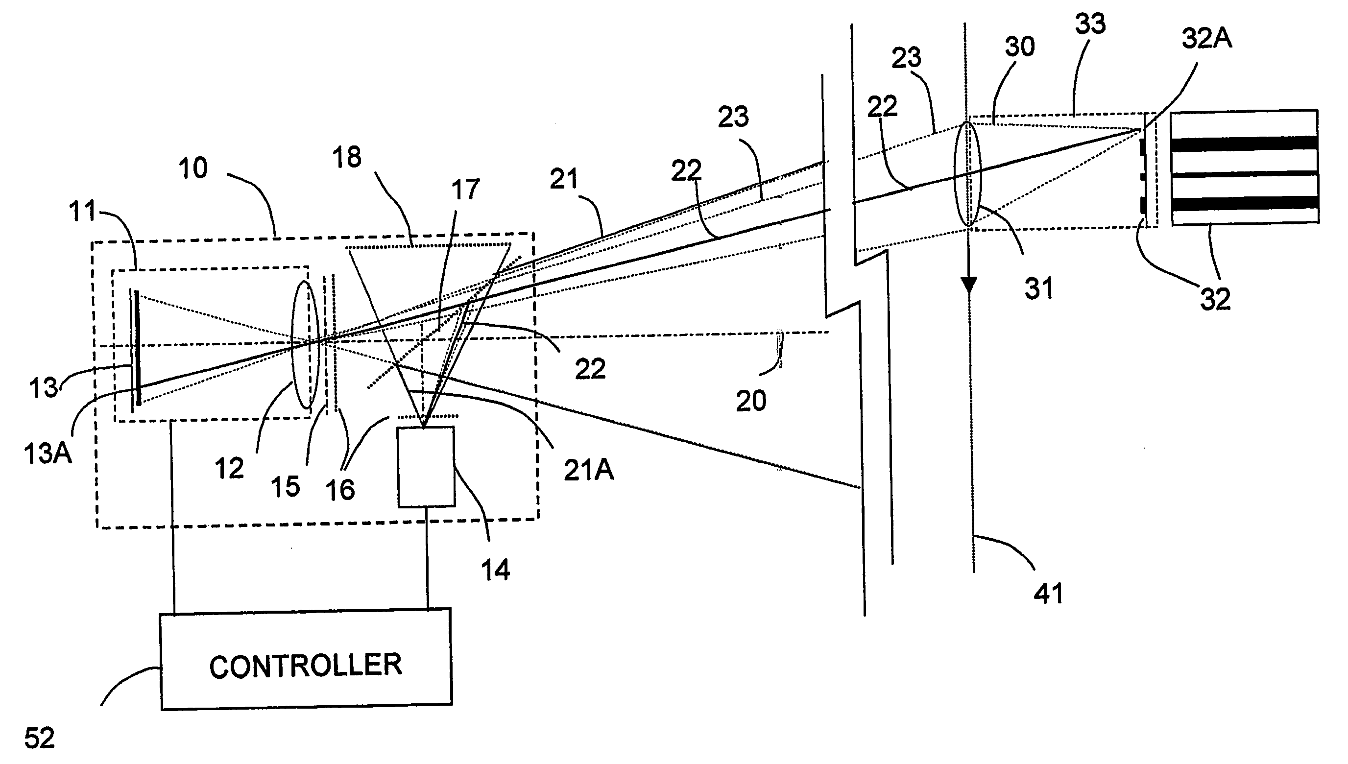
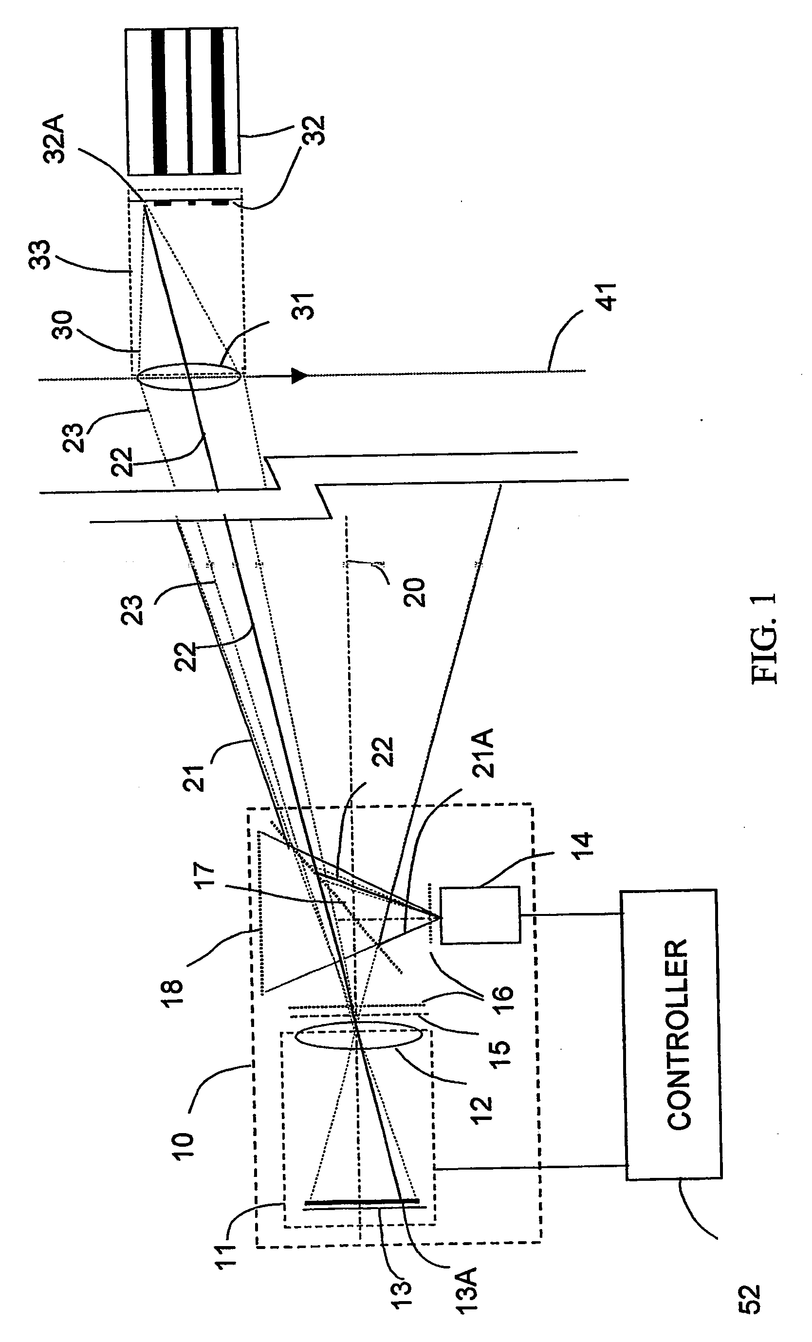
[0043]FIG. 1 shows a schematic layout of the system of the present invention comprising a moving tag reader, (MTR), 10, for automatic identification, speed assessment and position determination of moving tags, in accordance with a preferred embodiment of the present invention. The MTR 10 optionally comprises a camera 11 having a lens 12 and an imager 13, a light source 14 and a beam splitter 17. A controller 52 controls the light source 14 and camera 11 and also preferably comprises an image processor for processing images acquired by the camera of the entire field of view of the MTR In accordance with an embodiment of the present invention, light source 14 and camera 11 optionally have coincident optical axes 20 by means of a bore sight arrangement using beam splitter 17, and optionally have the same field of view 21 by suitable choice of the numerical aperture of the lens 12 and the cone of light 21A emitted by the light source. The light source can preferably be either a regular ...


PUM


Abstract

A method and apparatus for automatic certification, identification and tracking of remote objects in relative motion to a reading system, utilizing a novel tag affixed to an object and novel apparatus and techniques for automatically reading the tag information, its relative velocity, angle and position. The tag reader comprises an imaging system that undertakes real time image processing of the acquired images. Matching of the optical parameters of the imaging optics at the reader and the focusing optics at the tag ensure optical reliability and readability at large ranges. Novel types of tag designs are presented.

Description

FIELD OF THE INVENTION [0001] The present invention relates to the field of remote tracking systems, especially for use in determining the identity and motion of a moving remote object by means of an optical identity tag carried thereon. BACKGROUND OF THE INVENTION [0002] Various systems are known in the prior art that address the problem of automatically identifying tagged objects or vehicles in motion. These systems generally use radiation such as ultrasonic, radioactive, optical, magnetic or radio frequency radiation. Some of these systems have not received widespread acceptance because of excessive cost and insufficient reliability. [0003] Various optical systems, such as license plate recognition systems, are sensitive to lighting variations, cannot handle massive flows and necessitate the assistance of a human operator to analyze cumbersome images of license plates that the processing software cannot recognize. Other optical systems, based on barcode reading, generally have li...

Claims


Application Information

Patent Timeline
IPC IPC(8): G02B5/00G06K7/10
CPCG06K2017/0045G06K7/10722
Inventor STEKEL, AMIT
Owner STEKEL AMIT
Learn More