LED-based edge lit illumination system

a led-based edge light and illumination system technology, applied in the field of improved backlighting systems, can solve the problems of reducing conversion efficiency, reducing lumen output, and limiting the control of correlated color temperature (cct) of led based backlighting systems,

Active Publication Date: 2006-01-05
GE LIGHTING SOLUTIONS LLC
View PDF26 Cites 227 Cited by
  • Summary
  • Abstract
  • Description
  • Claims
  • Application Information

AI Technical Summary

Problems solved by technology

Although offering some advantages, conventional blue chip and yellow phosphor LED based backlighting systems offer limited control over correlated color temperature (CCT), color rendering index (CRI), and color gamut for the display.
Placing the phosphor next to the LED chip has been observed to reduce the conversion efficiency due to phosphor saturation effects, thermal quenching and other optical losses.
This can lead to significant reduction in lumen output, reducing the advantages of such backlighting systems.
In addition, saturation can lead to severe and undesirable changes in the color point of the device with variations in drive current.

Method used


Image

  • LED-based edge lit illumination system
  • LED-based edge lit illumination system
  • LED-based edge lit illumination system

Examples


first embodiment

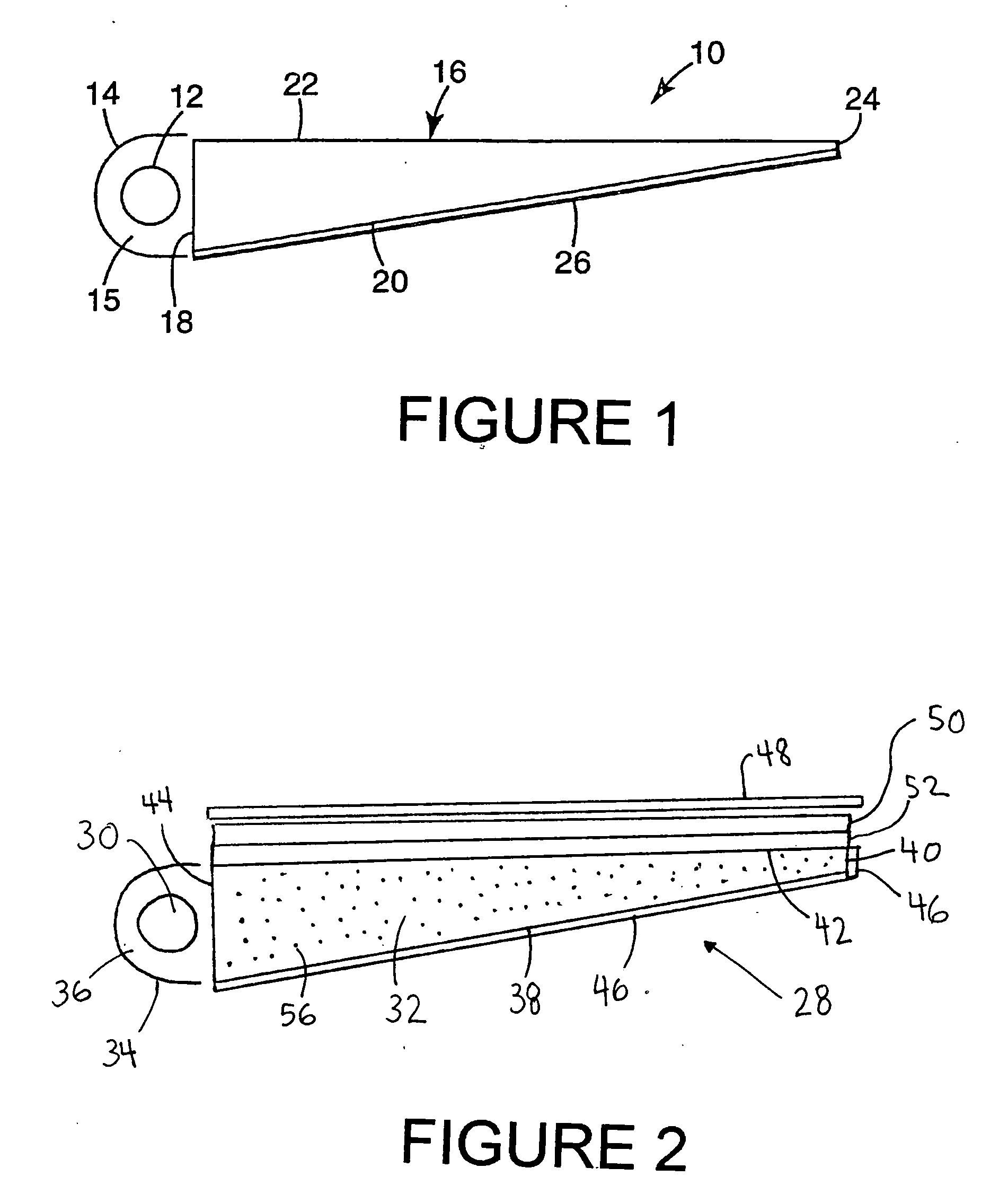
[0019]FIG. 2 shows a cross sectional view showing a portion of an LED backlighting device in accordance with the present invention. Backlighting device 28 includes an LED light source 30, a light guide 32, a light source reflector 34 surrounding the LED such that the light generated therefrom is concentrated towards the light guide. The light source reflector 34 may be reflective film that wraps around the LED light source 30 forming a cavity 36.

[0020] The LED light source may include any semiconductor visible or UV light source that is capable of producing, when combined with the phosphor composition, white light in the present embodiments. The preferred emission of the LED chip in the present invention will depend on the identity of the phosphors in the disclosed embodiments. However, the emission of the LED will generally have a wavelength in the range from about 250 to about 550 nm, which corresponds to an emission ranging from UV to green. Typically, the semiconductor light sou...

second embodiment

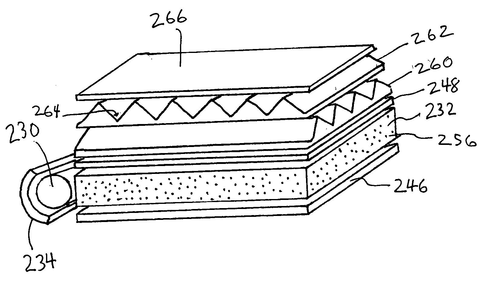
[0074] In a second embodiment, the phosphor or other radiation converting material is embedded or disposed within or on the surface of one or more of the light directing optics in addition or instead of the light guide. Thus, when present, the phosphor material may be disposed on a diffuser plate, brightness enhancement film, prisms, radiation reflection layer, etc. Alternately, the phosphor can be disposed in or placed on film layers placed on one or more surfaces of the light guide, including the output surface.

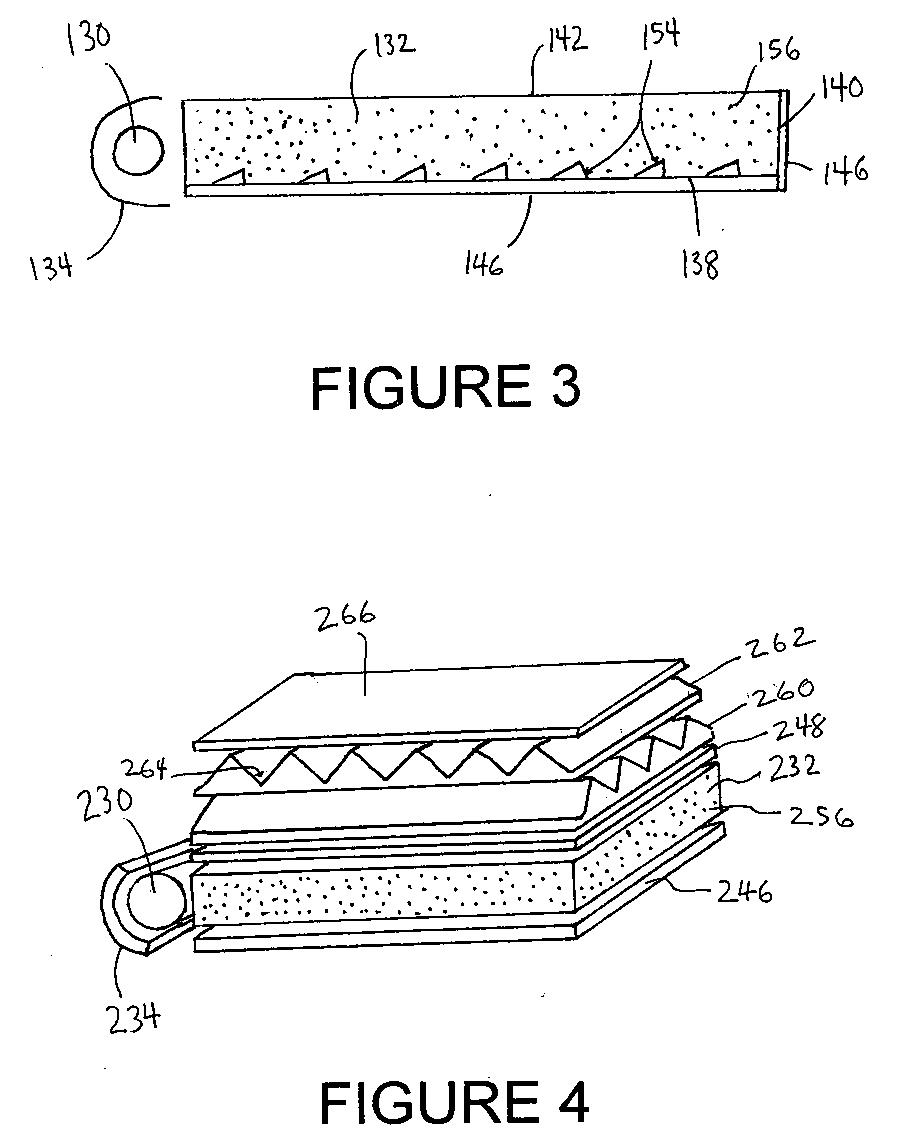
[0075]FIG. 3 shows an alternate embodiment of a backlighting system including a plurality of optical structures 154. With continued reference to FIG. 3, a slab shaped lightguide 132 includes an input edge surface 144, an opposing end surface 140, an output surface 142 and a back surface 138. Phosphor particles 156 are either dispersed in the lightguide (as shown) and / or positioned as a distinct layer (not shown) on the output surface 142 and, optionally, on other surfaces o...


PUM

PropertyMeasurementUnit
wavelengthaaaaaaaaaa
peak wavelengthaaaaaaaaaa

Abstract

An edge lit illumination system is directed to providing backlighting utilizing a luminescent impregnated lightguide. The apparatus includes an LED radiation source providing a first radiation and a lightguide optically coupled to the LED radiation source including a luminescent material embedded or coated on an output surface of the lightguide designed to absorb the first radiation, and emit one or more radiations. The illumination system may further include additional optical components such as reflective layers, for directing radiation striking the back surfaces of the light guide back into the lightguide, as well as diffusion layers, UV reflectors, and polarizers.

Description

FIELD OF THE INVENTION [0001] The present exemplary embodiments relate to an improved backlighting system. It finds particular application in conjunction with liquid crystal displays (“LCD's”), and will be described with particular reference thereto. However, it is to be appreciated that the present exemplary embodiment is also amenable to other like applications wherein a waveguide is used to shine light on a surface. BACKGROUND OF THE INVENTION [0002] Backlit display devices, such as liquid crystal display (LCD) devices, commonly use a slab or wedge-shaped lightguide. The lightguide distributes light from a substantially linear source, such as a cold cathode fluorescent lamp (CCFL), to a substantially planar output. The planar light output of the lightguide is used to illuminate the LCD. [0003] As is well known, the purpose of the lightguide is to provide for the distribution of light from the light source over an area much larger than the light source, and more particularly, subs...

Claims


Application Information

Patent Timeline
Patent Type & Authority Applications(United States)
IPC IPC(8): H01L33/00
CPCG02B6/0003G02B6/0031G02B6/0041G02B6/0053G02F1/133615G02B6/0065G02B6/0071G02F1/133603G02B6/0055
Inventor JACOB, CHERIANCHEN, CHEN-LUN HSINGRADKOV, EMILSRIVASTAVA, ALOK MANISETLUR, ANANT ACHYUTCOMANZO, HOLLY ANNSHIANG, JOSEPH
Owner GE LIGHTING SOLUTIONS LLC
Why Eureka
Try Eureka