Split gate type flash memory device and method of manufacturing the same

Inactive Publication Date: 2006-01-05
SAMSUNG ELECTRONICS CO LTD
View PDF9 Cites 11 Cited by
  • Summary
  • Abstract
  • Description
  • Claims
  • Application Information

AI Technical Summary

Benefits of technology

[0026] Since the floating gate and the control gate are formed to be self-aligned with the sidewall of the mask pattern using an etchback process, and not a photolithography process, a misalignment margin for compensating for misalignment caused by the photolithography process is not needed. Further, a limit

Problems solved by technology

In this arrangement, current flows between a source region and a drain region, irrespective of turn-on and turn-off of a selection memory cell, which causes all memory cells to perform an erroneous operation of on-state reading.
Accordingly, the nonvolatile memory device has difficulty in strictly controlling the threshold voltage.
Further, generating sufficient channel hot carriers for fast programming requires a high volta

Method used


Image

  • Split gate type flash memory device and method of manufacturing the same
  • Split gate type flash memory device and method of manufacturing the same
  • Split gate type flash memory device and method of manufacturing the same

Examples


Example

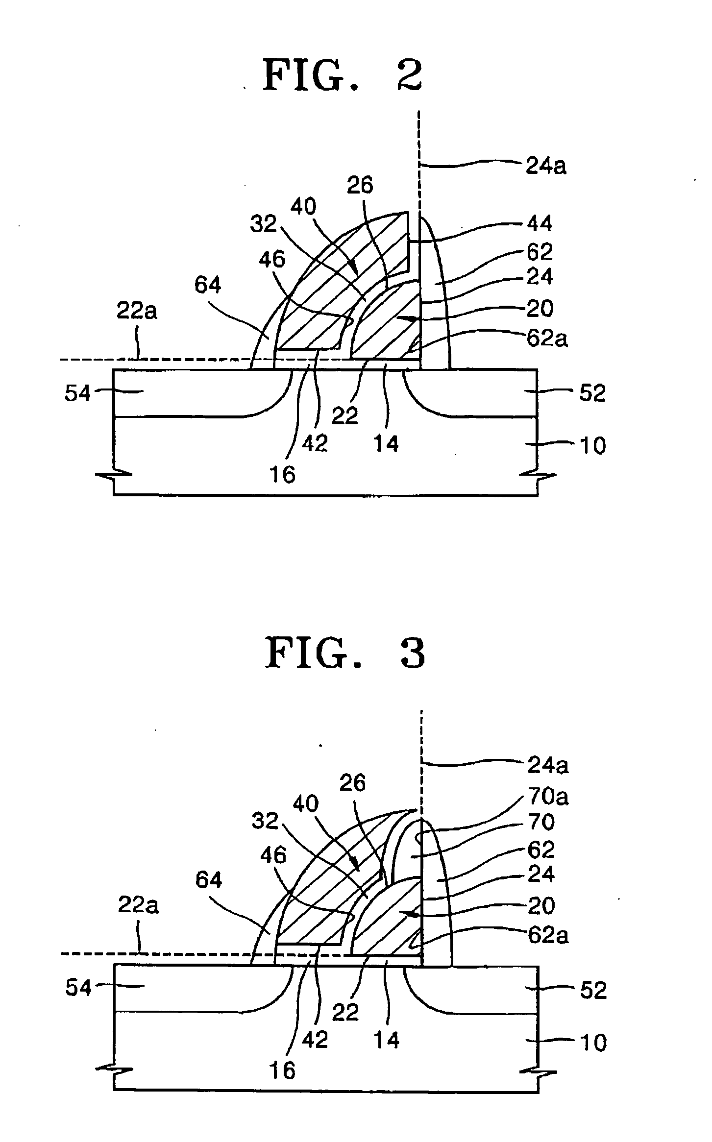
[0042] The second embodiment of FIG. 3 is substantially the same as the first embodiment, but differs from the first embodiment in that a third insulating spacer 70 is additionally formed on the curved surface 26 of the floating gate 20. The third insulating spacer 70 has a vertical sidewall 70a disposed on the extension line 24a of the second surface 24 of the floating gate 20. The third insulating spacer 70 may be formed of, e.g., oxide.

[0043] By forming the third insulating spacer 70, the bottom surface 46 of the control gate 40 has a shorter length than the curved surface 26 of the floating gate 20. The bottom surface 46 faces the curved surface 26 of the floating gate 20 with the inter-gate insulating film 32 interposed therebetween. More specifically, in the second embodiment, an overlap area of the floating gate 20 and the control gate 40 is reduced as compared to an overlap area in the first embodiment. Accordingly, a voltage applied to the control gate 40 has less affect o...

Example

[0060] In FIGS. 5A through 5E, like reference numerals as in the first embodiment described with reference to FIGS. 4A through 4I indicate like elements.

[0061] Referring to FIG. 5A, after the floating gate 120a is formed on the semiconductor substrate 100, as described with reference to FIGS. 4A through 4C, an insulating material, i.e., oxide, is deposited and etched-back over an entire surface of the resultant structure to form the third insulating spacer 270 on the vertical sidewall of the mask pattern 110 and on the curved surface 126 of the floating gate 120a.

[0062] Referring to FIG. 5B, the inter-gate insulating film 130 is formed on the floating gate 120a and the third insulating spacer 270, as described with reference to FIG. 4D.

[0063] Referring to FIG. 5C, the control gate 140a is formed at a sidewall of the third insulating spacer 270 and over the floating gate 120a in the self-alignment method, as described with reference to FIGS. 4E and 4F. By forming the third insulat...


PUM


Abstract

In a split gate type flash memory device, and a method of manufacturing the same, the device includes a memory cell array having a memory cell uniquely determined by a contact of a corresponding bit line and a corresponding word line, a floating gate formed on a semiconductor substrate to constitute the memory cell, the floating gate having a horizontal surface parallel to a main surface of the substrate, a vertical surface perpendicular to the main surface of the substrate, and a curved surface extending between the horizontal and vertical surfaces, a control gate formed over the curved surface of the floating gate in an area defined by an angle range of less than 90° between an extension line of the horizontal surface and an extension line of the vertical surface, and source and drain regions formed in an active region of the substrate.

Description

BACKGROUND OF THE INVENTION [0001] 1. Field of the Invention [0002] The present invention relates to a semiconductor memory device and a method of manufacturing the same. More particularly, the present invention relates to a split gate type flash memory device and a method of manufacturing the same. [0003] 2. Description of the Related Art [0004] Recently, demand has increased for an Electrically Erasable and Programmable ROM (EEPROM) or a flash memory for performing electrical input and output of data. A flash memory device has various fields of application since data is able to be erased and stored, and data can be preserved, even when power is not supplied. [0005] In a nonvolatile semiconductor memory device, memory cells are parallel-connected to a bit line such that a threshold voltage of a memory cell transistor is reduced to be less than a voltage (generally zero (0) V) applied to a control gate of a non-selection memory cell. In this arrangement, current flows between a sour...

Claims


Application Information

Patent Timeline
IPC IPC(8): H01L29/788H01L21/8238H01L21/8247H01L27/115
CPCH01L27/115H01L29/7885H01L29/42324H01L27/11521H10B69/00H10B41/30H10B99/00
Inventor RYU, EUI-YOULKWON, CHUL-SOONKIMKIM, YONG-HEEKIM, DAI-GEUNKIM, JOO-CHAN
Owner SAMSUNG ELECTRONICS CO LTD
Why Eureka
Try Eureka