Thin film coil, method of manufacturing the same, coil structure, and method of manufacturing the same

a technology of thin film coils and manufacturing methods, applied in the direction of transformers/inductance coils/windings/connections, inductance/transformers/magnets, etc., can solve the problems of deterioration of differential transmission characteristics, difficult to sufficiently reduce capacitance, and decrease in impedance, so as to improve differential transmission characteristics, minimize electric resistance (direct current resistance), and improve the effect of differential transmission characteristics

Inactive Publication Date: 2006-01-05
TDK CORPARATION
View PDF2 Cites 42 Cited by
  • Summary
  • Abstract
  • Description
  • Claims
  • Application Information

AI Technical Summary

Benefits of technology

[0010] A second object of the invention is to provide a coil structure capable of improving the differential transmission characteristic by reducing the capacitance as much as possible.
[0030] In the method of manufacturing a coil structure according to the invention, on the basis of the manufacturing method characteristic that a thin film coil is formed by using the method of manufacturing a thin film coil of the invention, only an existing thin film process is used for forming the thin film coil. Thus, the coil structure of the invention can be manufactured as easy as possible.

Problems solved by technology

Therefore, when considering the fact that the impedance by the capacitance is inversely proportional to the frequency, as the capacitance increases, the impedance decreases and it causes deterioration in the differential transmission characteristic.
However, in a conventional common mode choke coil, although it is necessary to reduce the capacitance as much as possible in order to improve the differential transmission characteristic, it is difficult to sufficiently reduce the capacitance mainly due to a structural factor of a thin film coil (coil patterns) and there is still room for improvement in reduction in the capacitance.

Method used


Image

  • Thin film coil, method of manufacturing the same, coil structure, and method of manufacturing the same
  • Thin film coil, method of manufacturing the same, coil structure, and method of manufacturing the same
  • Thin film coil, method of manufacturing the same, coil structure, and method of manufacturing the same

Examples


first embodiment

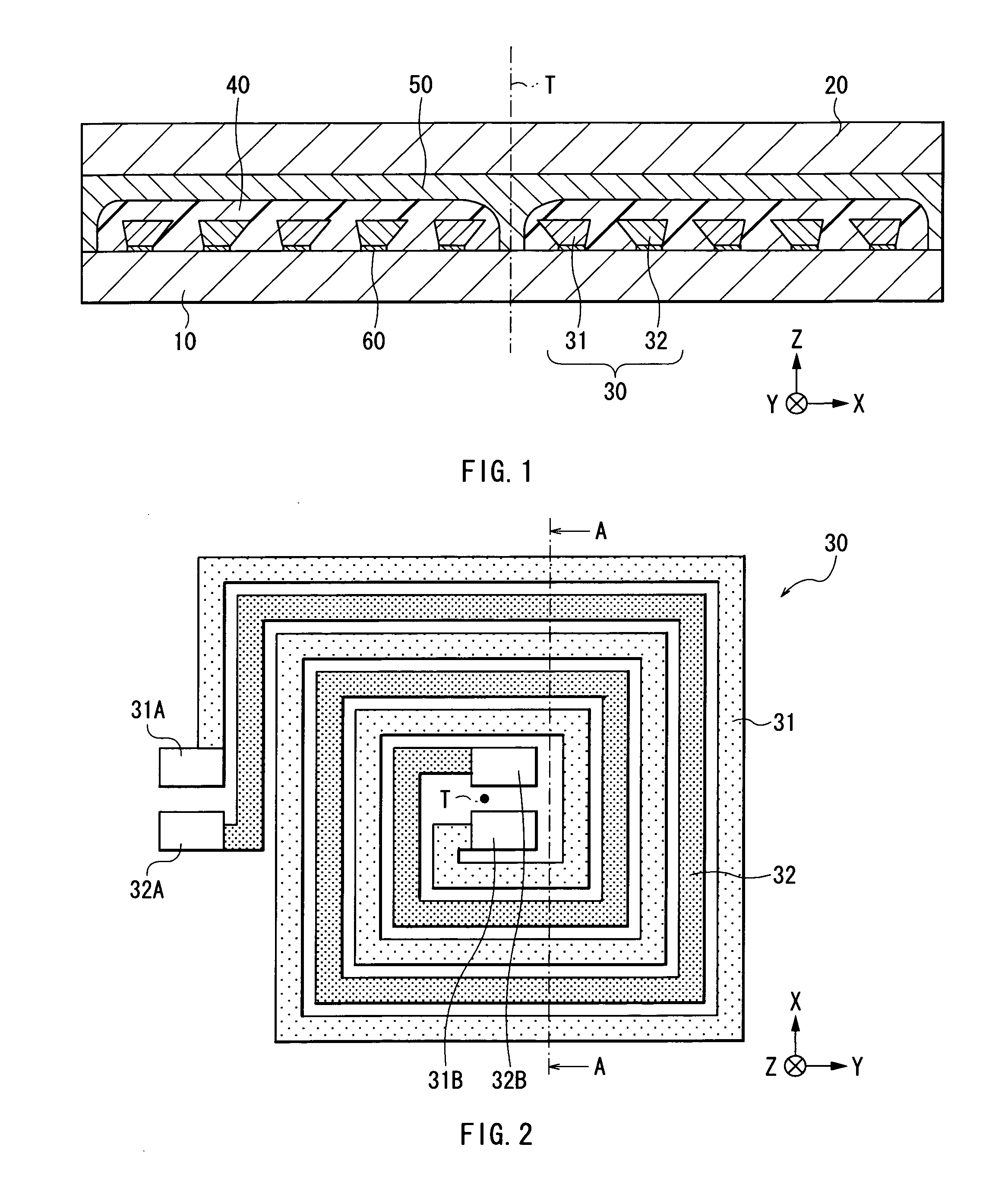
[0068] First, the configuration of a common mode choke coil as a “coil structure” according to a first embodiment of the invention will be described with reference toFIG. 1. FIG. 1 schematically shows a sectional configuration of a common mode choke coil. Since a “thin film coil” of the invention is a component of the common mode choke coil, the thin film coil will be also described hereinbelow.

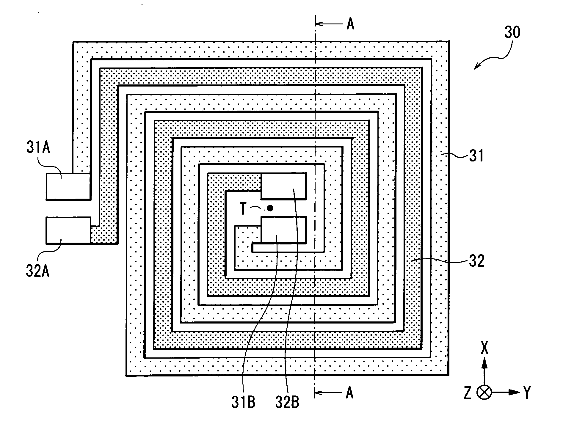
[0069] The common mode choke coil is used for, for example, reducing noise in a high frequency band and has a configuration that, as shown in FIG. 1, a thin film coil 30 is buried between two magnetic substrates as magnetic base bodies, specifically, a bottom magnetic substrate 10 and a top magnetic substrate 20 via an insulating layer 40, a magnetic layer 50, and a seed layer 60.

[0070] Each of the bottom and top magnetic substrates 10 and 20 is made of a magnetic material such as nickel iron alloy (NiFe (for example, Ni: 80% by weight and Fe: 20% by weight) which is so-called “Permalloy (t...

second embodiment

[0110] A second embodiment of the invention will now be described.

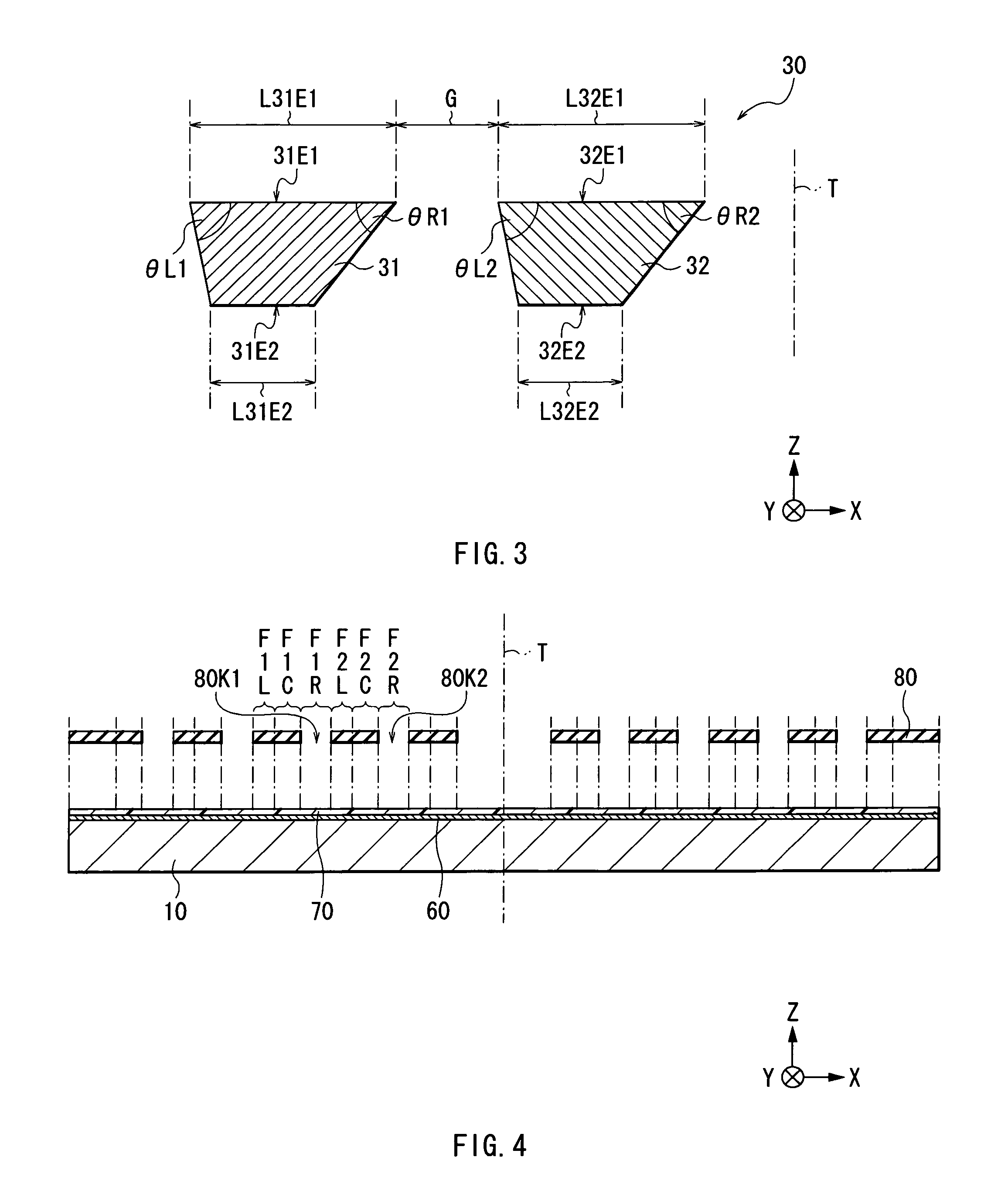
[0111]FIGS. 15 and 16 schematically show the configuration of a common mode choke coil as the “coil structure” according to the second embodiment of the invention. FIG. 15 schematically shows a sectional configuration of the common mode choke coil. FIG. 16 is a partially enlarged view of a sectional configuration of the common mode choke coil. In the FIGS. 15 and 16, the same reference numerals are designated to the same components as those of the first embodiment. Since the “thin film coil” of the invention is a component of the common mode choke coil, the thin film coil will be also described below.

[0112] As shown in FIG. 15, the common mode choke coil according to the second embodiment has a configuration which is similar to that of the common mode choke coil described in the first embodiment (refer to FIG. 1) except for the point that it has a thin film coil 130 including coil patterns 131 and 132 corresponding ...

third embodiment

[0137] A third embodiment of the invention will now be described.

[0138]FIGS. 28 and 29 are diagrams for explaining a process of manufacturing the common mode choke coil as the “method of manufacturing the coil structure” according to the third embodiment of the invention and correspond to FIGS. 6 and 8, respectively, which were referred to in the first embodiment. In the FIGS. 28 and 29, the same reference numerals are designated to the same components as those of the first embodiment. Since the “method of manufacturing a thin film coil” of the invention is a used to form the thin film coil 30 (the coil patterns 31 and 32) in a process of manufacturing the common mode choke coil according to a third embodiment, the method will be also described below.

[0139] In the method of manufacturing the common mode choke coil according to the third embodiment, the thin film coil 30 (the coil patterns 31 and 32) is formed by a forming process (refer to FIGS. 4 to 11) which is similar to the ma...


PUM

PropertyMeasurementUnit
thicknessaaaaaaaaaa
length L32E2aaaaaaaaaa

Abstract

The present invention provides a coil structure capable of improving a differential transmission characteristic by reducing capacitance as much as possible. A common mode choke coil is constructed so that a section of each of two coil patterns constructing a thin film coil has an inverted trapezoid shape which is bilaterally asymmetrical. Because of the structural characteristic that the section of each of the two coil patterns has an inverted trapezoid shape which is bilaterally asymmetrical, the facing area of the two coil patterns contributing to capacitance is minimized. Thus, the capacitance of the thin film coil can be reduced as much as possible.

Description

BACKGROUND OF THE INVENTION [0001] 1. Field of the Invention [0002] The present invention relates to a thin film coil including two coil patterns turned spirally in parallel with each other, a method of manufacturing the same, a coil structure having the thin film coil, and a method of manufacturing the same. [0003] 2. Description of the Related Art [0004] In recent years, in the information communication field and the like, a common mode choke coil is spread as a coil part for reducing noise in a high frequency band. For example, the common mode choke coil is used for preventing noise of a radio broadcast or the like from coming into a telephone line. [0005] The common mode choke coil has a configuration that, mainly, a thin film coil is buried between two magnetic substrates via an insulating layer. The thin film coil is generally constructed by including a coil pattern turned spirally. Examples of known common mode choke coils are a common mode choke coil including a thin film co...

Claims


Application Information

Patent Timeline
Patent Type & Authority Applications(United States)
IPC IPC(8): H01F5/00
CPCH01F17/0006H01F27/34H01L28/10H01F2017/0093H01F41/041
Inventor KAJI, RINAKAMIJIMA, AKIFUMIAOKI, SUSUMUTAKEO, KENJISATO, YOSHIKAZU
Owner TDK CORPARATION
Why Eureka
Try Eureka