Magnetic recording media for tilted recording

a recording media and magnetic recording technology, applied in the field of magnetic storage devices and magnetic recording media, can solve the problems of not giving materials or techniques, and the expected cost of tilted recording devices is about the same as currently available technologies

Inactive Publication Date: 2006-01-05
WESTERN DIGITAL TECH INC
View PDF9 Cites 36 Cited by
  • Summary
  • Abstract
  • Description
  • Claims
  • Application Information

AI Technical Summary

Benefits of technology

[0015] B=(Pt and/or Pd) with a magnetic eas

Problems solved by technology

Tilted recording devices can be expected to cost about the same as currently available technologies.
In their theoretic

Method used


Image

  • Magnetic recording media for tilted recording
  • Magnetic recording media for tilted recording
  • Magnetic recording media for tilted recording

Examples


first embodiment

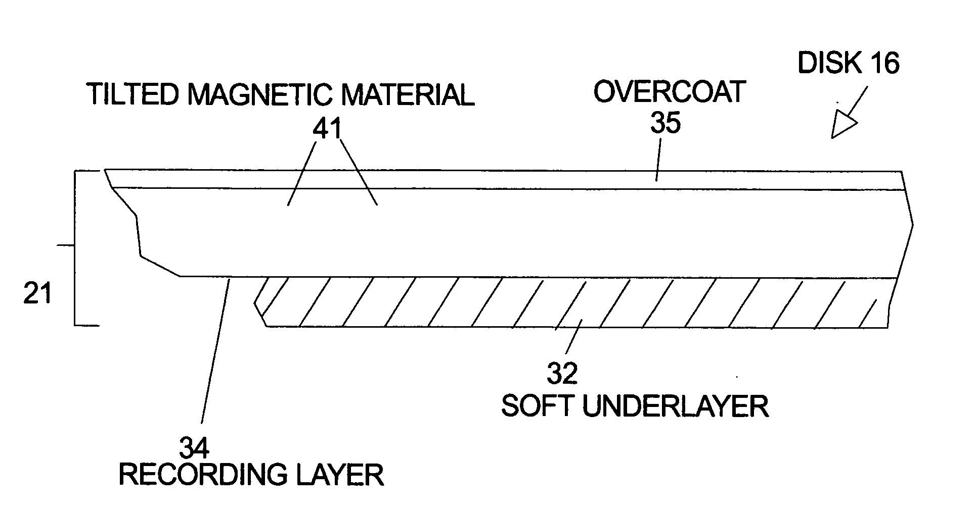
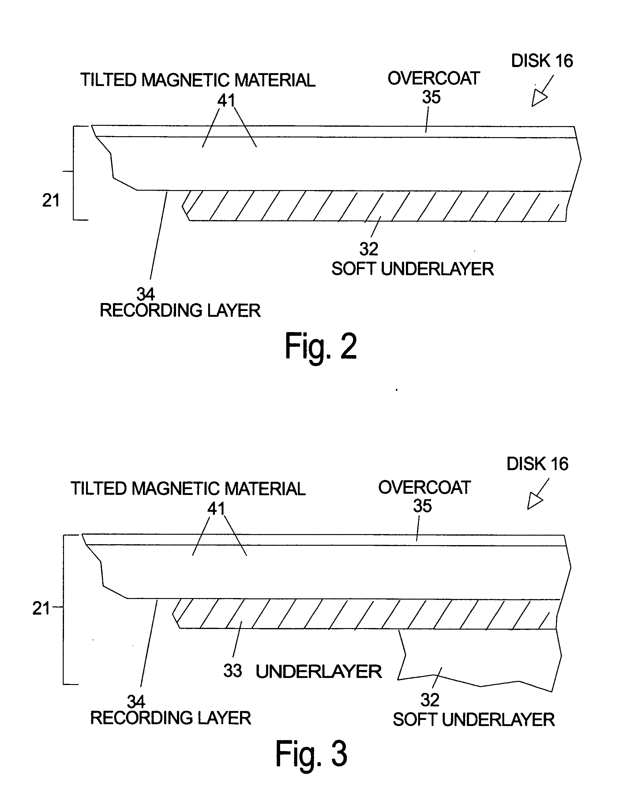
[0023] the invention is illustrated in FIG. 2 which shows a section of the thin films 21 on a disk 16 for according to an embodiment of the invention. The recording layer 34 comprises (111) oriented, granular L10 magnetic material 41 deposited over a soft underlayer (SUL) 32 for the purpose of tilted recording with a perpendicular write field. The magnetic properties of the recording layer 34 are selected to provide an easy axis of switching (anisotropy) which is tilted out of the plane of the thin films on the surface of the disk. The magnetic easy axis of the magnetic material is approximately 36 degrees out the plane of the film. The thicknesses of the films in the drawings are not according to scale. The actual thicknesses can be determined according to the prior art except where noted herein. Preferably the L10 recording layer thickness is less than 20 nm and the distance between the bottom of the L10 media and top of the SUL is less than 20 nm. The average grain size in the pl...

second embodiment

[0028] the invention is illustrated in FIG. 3 which shows a section of the thin films 21 on a disk 16 with an intermediate layer 33 deposited between the recording layer 34 and SUL 32. The intermediate layer material is chosen to have close lattice matching to the L10 film. In one embodiment the invention includes a lattice-matched fcc metal layer with (111) texture as an intermediate layer for epitaxial L10 tilted media. For example, CoPt has a-axis lattice constant of 3.80 angstroms and c-axis lattice constant of 3.68 angstroms while FePt has a=3.85 angstroms and c=3.71 angstroms. Fcc metals that are well lattice-matched include platinum (a=c=3.92 angstroms), palladium (a=c=3.89 angstroms), iridium (a=c=3.84 angstroms), and rhodium (a=c=3.80 angstroms). Alternatively, hcp metals with (100) texture have a triangular close-packed surface structure and can also be used to establish the epitaxy for (111) oriented L10 tilted media. For example, ruthenium, rhenium, and osmium have “effe...

third embodiment

[0036] the invention is illustrated in FIG. 4 which shows a section of the thin films 21 on a disk 16 with a recording layer 34M, an intermediate layer 33, and SUL 32. Recording layer 34M includes matrix material 42 which forms grain boundaries. The recording layer 34M is formed by co-deposition of grain boundary material with the tilted magnetic material 41. The materials will self-segregate during the deposition process and the result is magnetic isolation of the grains of L10 material by the matrix material. For example Si and O may be co-deposited to form amorphous SiOx matrix material between the L10 grains. The matrix material serves to reduce intergrain coupling. Preferably the grain boundary material is approximately 1 nm thick. Other dopants such as Cr, Ag, Au, Cu, Ta, or B may be added to the recording layer which tend to arrange themselves at grain boundaries and reduce intergrain coupling. Other materials that can also be co-deposited to form amorphous material between g...


PUM


Abstract

A recording medium according to the invention has a magnetic recording layer with an L10 magnetic material deposited with a (111) preferred orientation and soft underlayer (SUL). One set of embodiments includes an intermediate layer (seed layer or underlayer) between the L10 media and SUL. The intermediate layer can be a close-packed surface structure (triangular lattice) to promote (111) orientation of the L10 media. For example, the intermediate layer can be a (111) oriented, face-centered-cubic (fcc) material such as platinum, palladium, iridium, rhodium, FePt, FePd, or FePdPt alloys; or the intermediate layer can be a (100) oriented hexagonal-close-packed (hcp) material such as ruthenium, rhenium, or osmium. Alternatively, the intermediate layer can be an amorphous material. The L10 recording layer of the invention can be deposited with a matrix material to form grain boundaries and provide magnetic isolation of the grains of L10 material.

Description

FIELD OF THE INVENTION [0001] The invention relates to magnetic storage devices and magnetic recording media for magnetic recording and more particularly to thin film magnetic media with a preferred orientation of the easy axis of magnetization tilted out of the surface plane of the media. BACKGROUND OF THE INVENTION [0002] A typical prior art disk drive system 10 using perpendicular recording is illustrated in FIG. 1. In operation the magnetic transducer (head) 14 is supported by the suspension (not shown) as it flies above the rotating disk 16. The magnetic transducer 14, usually called a “head” or “slider,” is composed of elements that perform the task of reading and writing magnetic transitions. In a disk drive using perpendicular recording the recording head is designed to direct magnetic flux through the recording layer in a direction which is perpendicular to the plane of the disk. Typically the disk 16 for perpendicular recording has thin films 21 including a hard magnetic r...

Claims


Application Information

Patent Timeline
IPC IPC(8): G11B11/00B32B3/02G11B5/82G11B5/64G11B5/73G11B5/84
CPCG11B5/65G11B5/84G11B5/7325G11B5/667G11B5/012G11B5/1278G11B5/743G11B5/82G11B5/7368G11B5/7377G11B5/658G11B5/674G11B5/657
Inventor STIPE, BARRY CUSHINGTHIELE, JAN-ULRICH
Owner WESTERN DIGITAL TECH INC
Why Eureka
Try Eureka