
Dental lamp particularly for medical and dental surgeries

a technology for dental surgery and dental lamps, which is applied in the field of dental lamps particularly for medical and dental surgeries, can solve the problems of inability to use the orientable lamp with complete ease, the element entails an increase in size, and the overheating of the lamp body is extremely negative for correct operation, etc., and achieves the effect of low heat emission

Inactive Publication Date: 2006-01-05
EURODENT
View PDF16 Cites 24 Cited by
  • Summary
  • Abstract
  • Description
  • Claims
  • Application Information

AI Technical Summary

Benefits of technology

[0017] The aim of the present invention is to obviate the cited drawbacks and meet the mentioned requirements, by providing a dental lamp particularly for medical and dental surgeries that complies with currently applicable statutory provisions and has a low heat emission.
[0020] Another object of the present invention is to have an emitted light beam that is substantially free from infrared components and optionally has a reduced ultraviolet component, in order to avoid the curing of photopolymerizing materials.
[0021] Another object of the present invention is to reduce considerably the weights with respect to a conventional lamp by not requiring the presence of parabolic reflectors.
[0022] Within this aim and these objects, another object of the present invention is to provide a dental lamp that is simple, relatively easy to provide in practice, safe in use, effective in operation, and has a relatively low cost.

Problems solved by technology

Overheating of the lamp body is extremely negative for correct operation, since the components age precociously due to the thermal stress and further work in conditions that are far from the ones that provide maximum efficiency.
The presence of this element entails increases in size (due to the installation spaces but also to the provision of the air circuit), from the point of view of energy consumption (caused by the electric power consumption of the motor that drives the fan), in weight (due to the insertion of all the components of the cooling circuit) and most of all noise.
Therefore, when the surgeon operates by using these materials, he cannot use the orientable lamp with complete ease, since said lamp reduces considerably the curing times of said materials.
The average life of halogen lamps is rather short, and accordingly said lamps must be replaced frequently; further, in the final step of their life their light flux degrades considerably and sometimes does not fall within the parameters set by the standards.

Method used


Image

  • Dental lamp particularly for medical and dental surgeries
  • Dental lamp particularly for medical and dental surgeries
  • Dental lamp particularly for medical and dental surgeries

Examples


Embodiment Construction

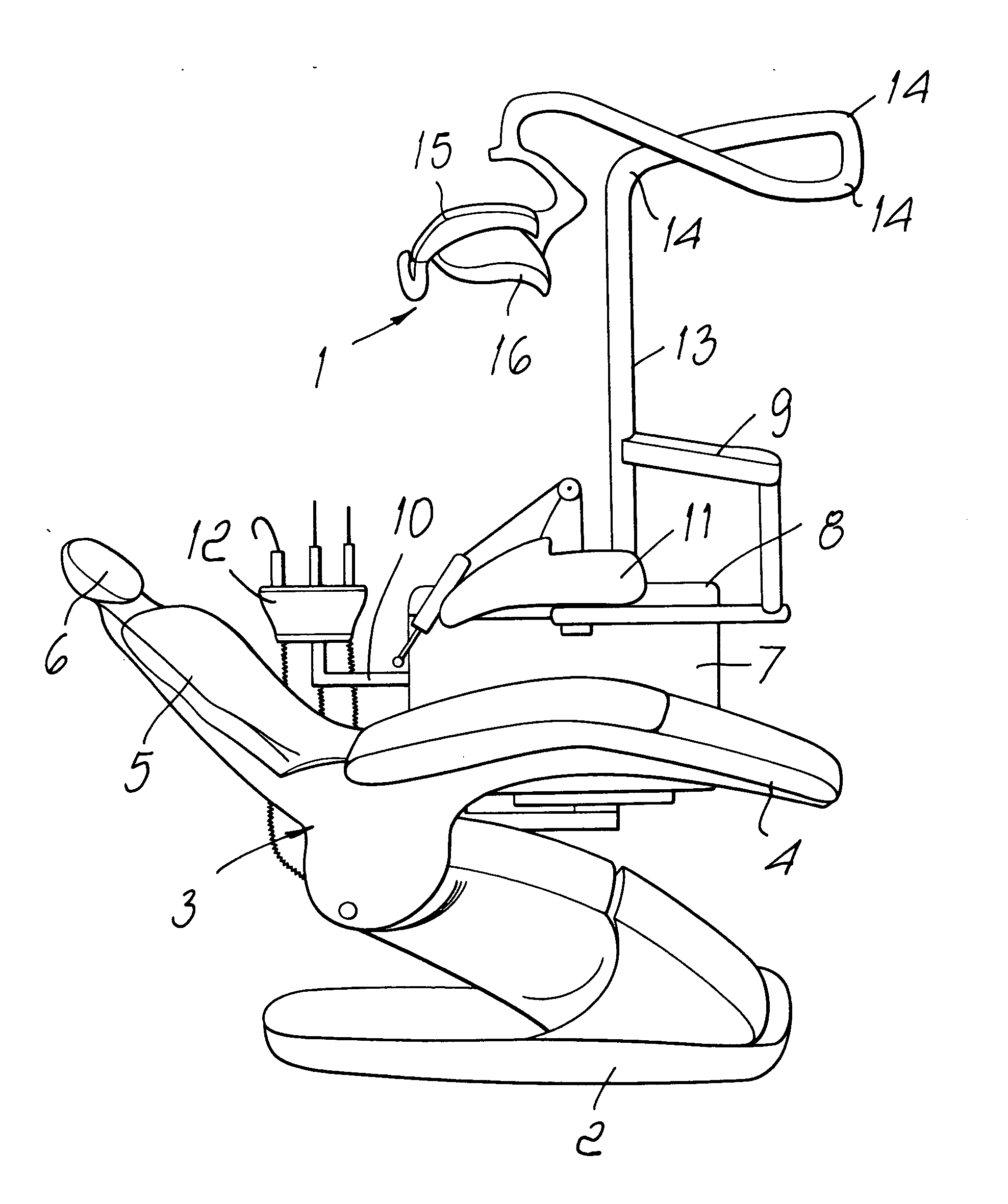
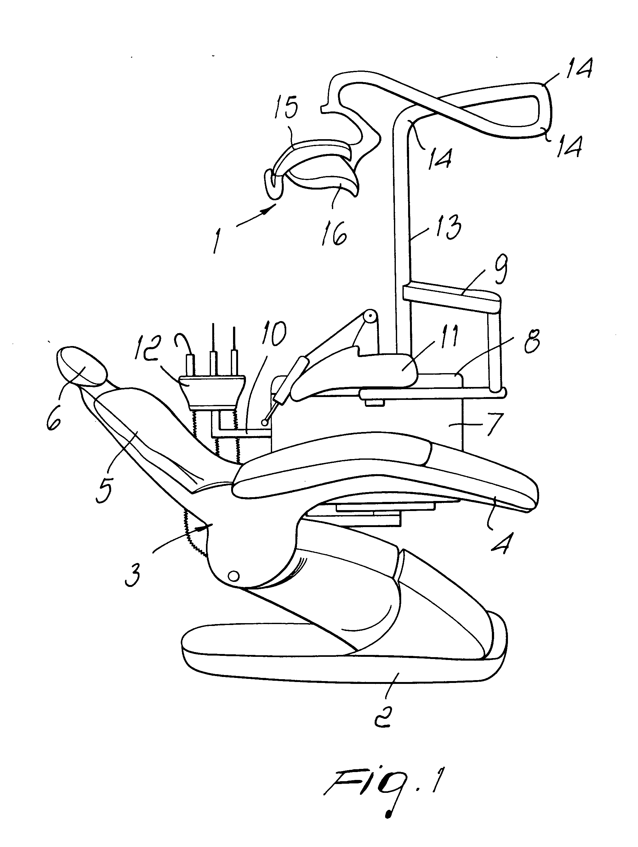
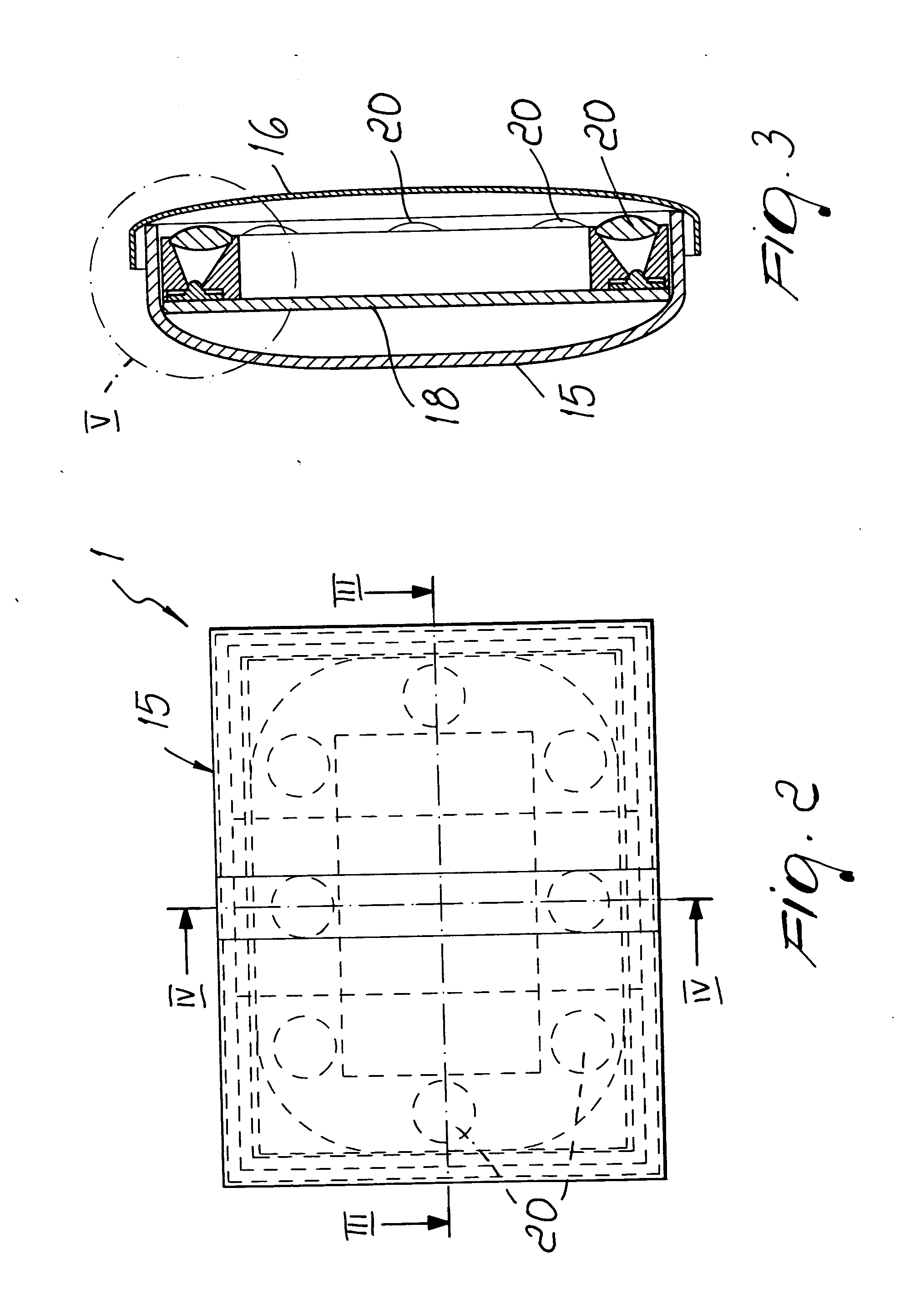
[0030] With reference to the figures, the reference numeral 1 generally designates a dental lamp particularly for medical and dental surgeries.

[0031] The dental lamp 1 is suitable for installation on apparatuses of dental studies that are constituted by a footing 2, which rests on the ground and through which they are connected to the electrical, hydraulic and compressed air supplies, by a chair 3 (mounted on the footing 2), and by a plurality of auxiliary elements for the surgeon.

[0032] The footing 2 is generally suitable to move vertically the components that are associated with it by way of the presence of traction elements (not shown in the figure), which are generally constituted by an electric motor and corresponding gears or by a hydraulic piston.

[0033] The chair 3 on which the patient lies comprises a seat 4, a back 5 and a headrest 6, all of which can move with respect to each other in order to meet the requirements of the patients and of the surgeon.

[0034] Laterally to...


PUM


Abstract

A dental lamp particularly for medical and dental surgeries, comprising an orientable arm that is rigidly coupled at one of its ends to a fixed structure and has the opposite end rotatably associated with a box-like body provided with a screen and a light source. The light source comprises a plurality of luminescent diodes, known as LEDs, which are aligned with respective guides for the emitted light beam, the beam emission directions of all the diodes being substantially convergent.

Description

[0001] The present invention relates to a dental lamp particularly for medical and dental surgeries. BACKGROUND OF THE INVENTION [0002] In dental surgeries it is necessary to supplement the diffuse ambient light with a beam of light that is localized on the part of the patient to be analyzed (in this case, the mouth). [0003] The light source required to provide this type of localized light is therefore a orientable lamp, which is generally mounted on a movable arm (so as to be able to direct the light beam exactly in the chosen point) with an intensity, frequency and color temperature of the emitted beam that are clearly defined by standard parameters. [0004] Currently applicable standards prescribe conditions regarding the light spot generated by the lamp on a surface that is at a distance of 700 mm (reference plane) from the emission point. The luminous intensity must be comprised between 75% and 100% of the maximum luminous intensity within a circle having a diameter of 50 mm tha...

Claims


Application Information

Patent Timeline
IPC IPC(8): A61B1/06F21S8/00
CPCF21W2131/202F21Y2115/10F21V13/04
Inventor KOKENY, ALESSANDROBRUNETTI, DOMENICO
Owner EURODENT
Learn More