
Sequential dilator system

Inactive Publication Date: 2006-01-05
SYNTHES USA
View PDF68 Cites 155 Cited by
  • Summary
  • Abstract
  • Description
  • Claims
  • Application Information

AI Technical Summary

Benefits of technology

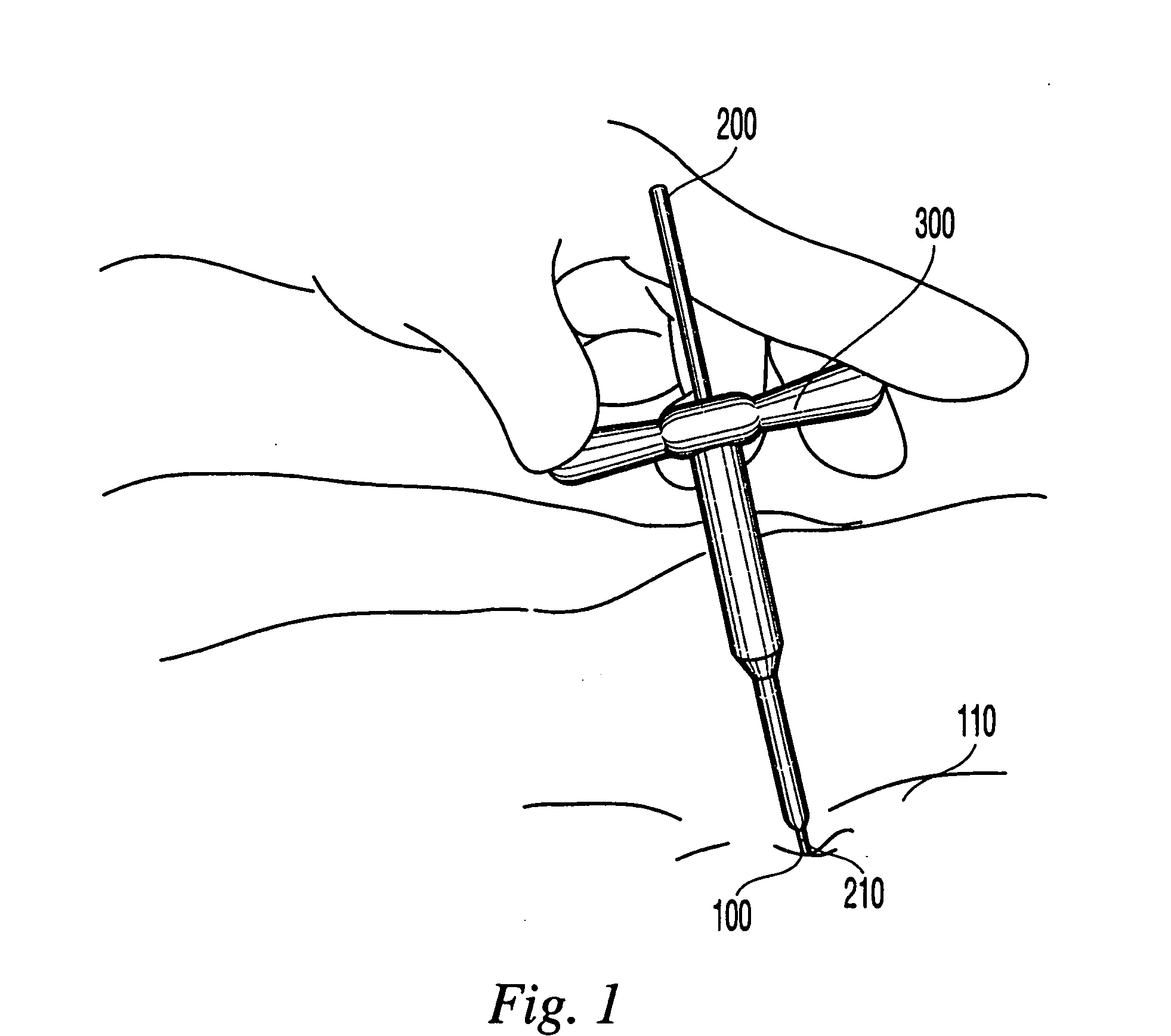
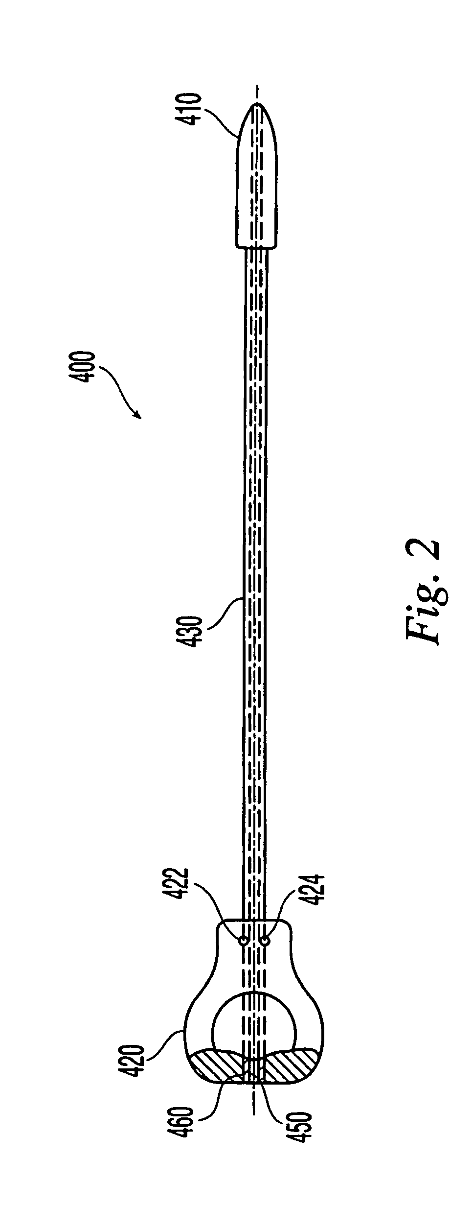
[0004] The dilator may comprise a handle suitable for grasping by a user and a series of dilator tubes of increasing diameter and shorter lengths, all with a tapered end for insertion into a patient. Preferably, the handle contains two or more sections of different internal diameter, each section including a dilator tube retaining mechanism. The different diameter sections of the handle match the outside diameters of the dilator tubes, which also include handle-engaging surfaces on the end opposite that inserted into the patient to mate with the dilator tube retaining mechanisms of the handle. There may be multiple grooves or other handle-engaging surfaces in the end of the dilator tubes that can be used to assist in grasping the dilator tubes and / or for use in a color coding system to indicate lengths, diameters, materials, etc. The handle may also have a window that allows the surgeon to determine when a dilator tube has engaged one of the ball detents of the handle. The internal diameters of the handle and outer diameters of the dilator tubes may further have matching flats to prevent relative rotation between the handle and dilator tubes.

Problems solved by technology

Problems associated with the surgical instruments and systems commonly used to provide such an “open incision” include the size of the instruments, which may be large and may occupy a significant portion of the surgical space to allow the surgeon a sufficiently large field in which to work.

Method used


Image

  • Sequential dilator system
  • Sequential dilator system
  • Sequential dilator system

Examples


Embodiment Construction

[0020] While the description of the dilator system of this invention will be discussed primarily in relation to spinal surgery, it should be understood that the system will find use in other areas of surgery in which a surgeon wishes to gain access to an internal cavity by cutting the skin and enlarging an incision in a body wall so that surgical instruments can be inserted to perform a desired surgical procedure. For example, the dilator system may be used to create an incision 100 to provide access to the posterior spine through which pedicle screws may be percutaneously installed in one or more selected vertebra. Alternatively, the dilator system may be used to create an incision to access an intervertebral disc space for performance of a minimally invasive discectomy procedure and / or spinal fusion procedure, including the implantation of one or more intervertebral implants.

[0021] As shown in the accompanying figures, the dilator system may comprise a bullet-shaped dilator instr...


PUM


Abstract

The present invention is directed to a sequential dilator for use in surgery and a method for using the sequential dilator. The sequential dilator may have a bullet-shaped dilator and a plurality of dilator tubes with a removable handle. The method may include inserting a guide wire through an incision into a patient's vertebra and subsequently inserting the bullet-shaped dilator and dilator tubes with tapered ends and of increasing size into the incision to increase the size of the incision. A kit including the components necessary for the method is also disclosed.

Description

FIELD OF THE INVENTION [0001] The present invention relates generally to a sequential dilator system, and more particularly to a sequential dilator system for use in surgery in creating access openings to the posterior spine for discectomy, interbody fusion, and pedicle screw fixation. BACKGROUND OF THE INVENTION [0002] The subject disclosure relates to minimally invasive surgical procedures and apparatus, and more particularly to a system for sequentially dilating an incision for performing minimally invasive surgery on the spine. A variety of retractors and dilation systems have been used to provide a traditional “open-incision” approach to the posterior spine, as well as for providing the more modern “minimally invasive” access to the spine. Problems associated with the surgical instruments and systems commonly used to provide such an “open incision” include the size of the instruments, which may be large and may occupy a significant portion of the surgical space to allow the sur...

Claims


Application Information

Patent Timeline
IPC IPC(8): A61M29/00
CPCA61B17/3417A61B17/3421A61M29/00A61B2017/0046A61B2017/00261A61B17/02A61B17/34
Inventor BINDER, LAWRENCE J. JR.GERBER, DAVID
Owner SYNTHES USA
Learn More