Method and assembly system for manufacturing an assembled camshaft

Inactive Publication Date: 2006-01-12
DAIMLER AG
View PDF12 Cites 33 Cited by
  • Summary
  • Abstract
  • Description
  • Claims
  • Application Information

AI Technical Summary

Benefits of technology

[0009] For manufacturing the camshafts, an assembly system is used which includes rotatable drums for accommodating the shafts to be fitted, the cooling lances, and the cams. The cams are heated and the shafts are cooled down in these drums. The drums are situated with respect to one another in such a way that their rotational axes are parallel; their rotary motions are adjusted to one another in such a way that, at the time of assembly, the axis of the shaft to be fitted, the axes of the cams to be threaded onto this shaft, and the axis of the cooling lance are collinear with one another. The assembly system advantageously includes an axially displaceable counterholder with the ai

Problems solved by technology

If the hardened cams are heated to temperatures above 200° C.

Method used


Image

  • Method and assembly system for manufacturing an assembled camshaft
  • Method and assembly system for manufacturing an assembled camshaft
  • Method and assembly system for manufacturing an assembled camshaft

Examples


Embodiment Construction

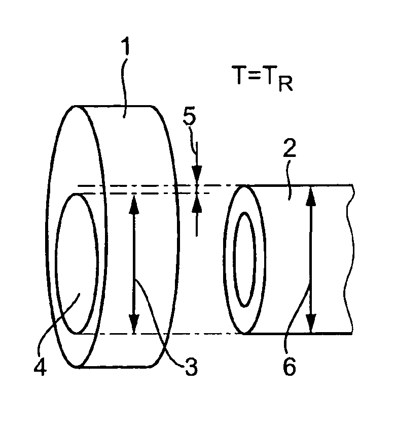
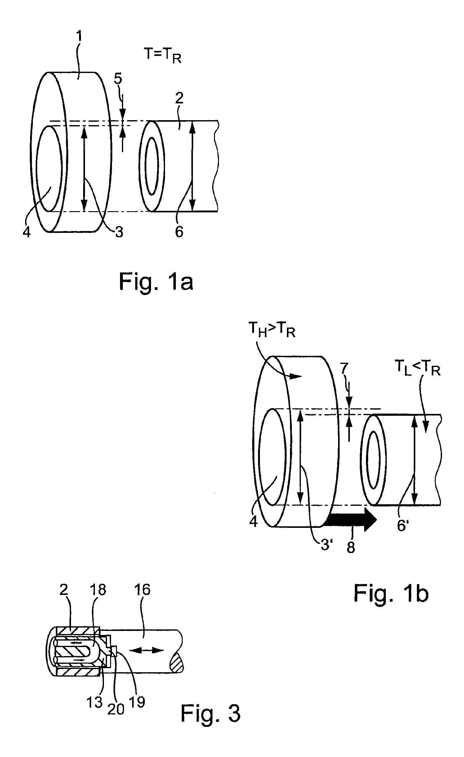
[0028]FIG. 1 shows a schematic representation of a hardened cam 1 which is to be shrunk onto a hollow shaft 2. In order to ensure a firm hold of cam 1 on hollow shaft 2, internal diameter 3 of cam opening 4 at room temperature TR is smaller then external diameter 6 of shaft 2 by what is called a “bite”5. If shaft 2 is cooled down to a temperature TLR, its external diameter is reduced to a value 6′; if cam 1 is heated to a temperature TH>TR, internal diameter 3′ of cam opening 4 increases with the effect that internal diameter 3′ of cam opening 4 is larger than external diameter 6′ of shaft 2 by what is called a “joint clearance”7 so that heated cam 1 may be slid onto cooled shaft 2 (arrow 8 in FIG. 1b). During cooling down of cam 1 and heating of shaft 2, cam 1 is shrunk onto shaft 2 along with the temperature equalization, “bite”5 preventing cam 1 from slipping on shaft 2.

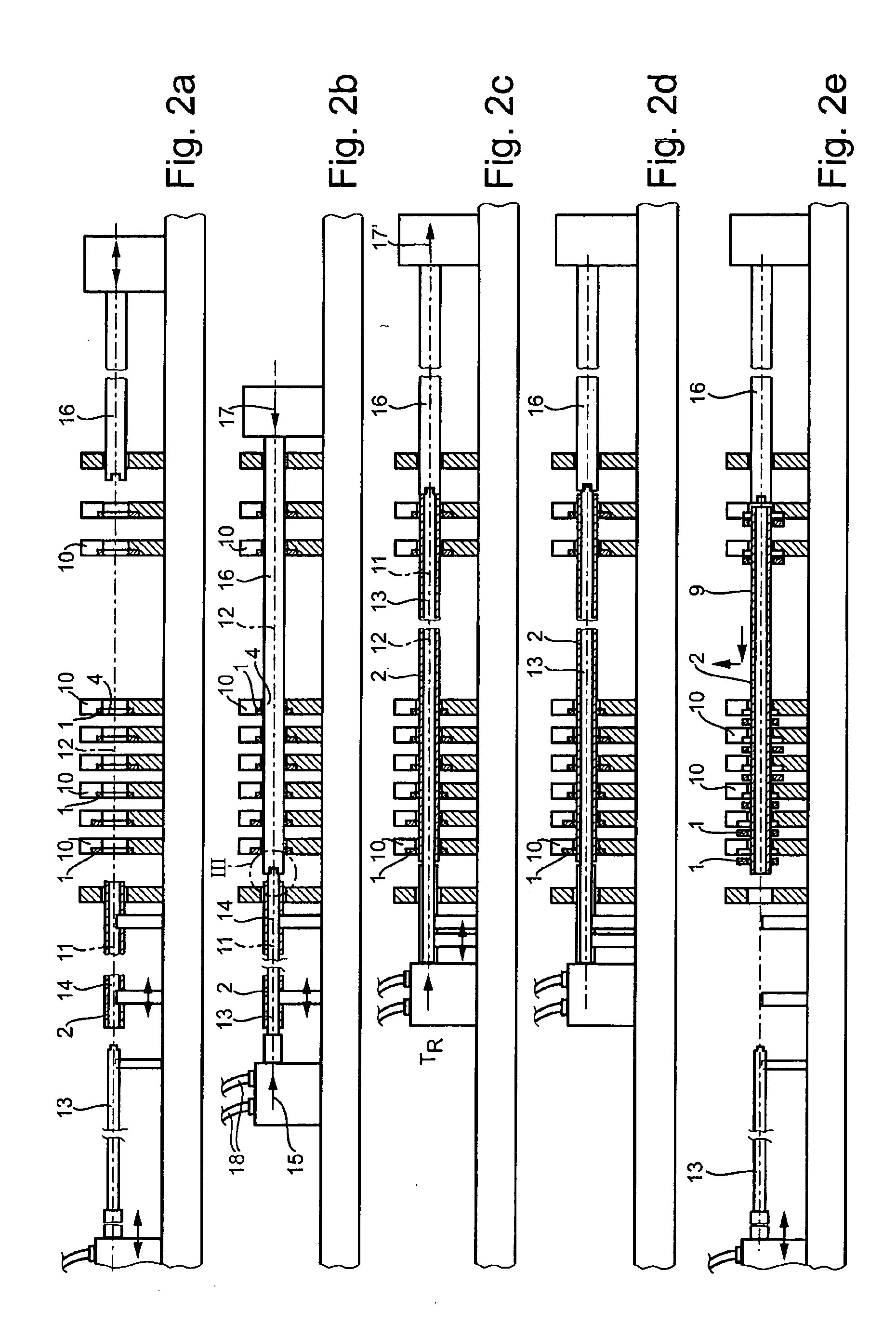
[0029]FIGS. 2a through 2e show a schematic representation of the process steps involved in carrying out the sh...


PUM

PropertyMeasurementUnit
Temperatureaaaaaaaaaa

Abstract

A method and an assembly system for manufacturing an assembled camshaft having a metallic shaft and at least one shrunk-on cam, includes initially heating the at least one cam, threading the at least one cam onto the shaft in a predetermined position in the heated state, and subsequently shrinking the at least one cam onto the shaft due to a cooling down. The shaft is cooled down prior to thread-on of the cams so that the cams are shrunk onto the shaft due to a temperature equalization which includes heating of the shaft and cooling down of the cams. The assembly system includes multiple drums in which the shafts and the cams to be fitted are accommodated and cooled and/or heated. The shafts are cooled preferably with the aid of a cooling lance inserted into a hollow space of the shaft.

Description

[0001] Priority is claimed to German Patent Application No. DE 10 2004 032 587.1, filed on Jul. 6, 2004, the entire disclosure of which is incorporated by reference herein. [0002] The present invention relates to a method for manufacturing an assembled camshaft made up of a metallic shaft including shrunk-on cams. Furthermore, the present invention relates to an assembly system for carrying out this method. BACKGROUND [0003] A shrink-on method for manufacturing an assembled camshaft made up of a metallic hollow shaft and multiple cams is described in DE 32 47 636 C2, which is incorporated by reference herein. The cams are heated, threaded onto the shaft using an elevated temperature with respect to the shaft, and brought into the correct position there using a positioning device. A formfitting shrink joint between the cams and the shaft is achieved due to the subsequent temperature equalization between the cams and the metallic shaft. [0004] In order to be able to thread the cams on...

Claims


Application Information

Patent Timeline
IPC IPC(8): B23P11/02
CPCB23P11/025B23P2700/02Y10T29/49865F16H53/025Y10T29/49286F01L1/047F16D1/0858
Inventor QUAAS, RALF
Owner DAIMLER AG
Why Eureka
Try Eureka