Thermoelectric conversion module

a technology of conversion module and thermal insulation, which is applied in the direction of thermoelectric devices with peltier/seeback effect, basic electric elements, electric apparatus, etc., can solve the problems of weak strength and fragile, unsuitable industrial mass production, and inability to further upsize, so as to achieve less heat absorption and heat, and low emissivity. , the effect of less heat absorption

Inactive Publication Date: 2006-01-12
CENTRAL RESEARCH INSTITUTE OF ELECTRIC POWER INDUSTRY +1
View PDF3 Cites 77 Cited by
  • Summary
  • Abstract
  • Description
  • Claims
  • Application Information

AI Technical Summary

Benefits of technology

[0011] To achieve these objects, a thermoelectric conversion module of the present invention includes at least a pair of thermoelectric semiconductors, a heat source side electrode portion installed on a plane of a high-temperature heat source side of the thermoelectric semiconductors for electrically connecting the thermoelectric semiconductors in series, a radiation side electrode portion installed on a plane of a low-temperature heat source side of the thermoelectric semiconductors for electrically connecting the thermoelectric semiconductors in series, a heating plate for covering the heat source side electrode portion and receiving heat from a high-temperature heat source, a cooling plate for covering the radiation side electrode portion and conveying the heat to a low-temperature heat source, a sliding member having high heat conductivity and intervening at least between the heat source side electrode portion and the heating plate, and a coupling plate for coupling the cooling plate to the heating plate and sandwiching the thermoelectric semiconductors and the electrode portions between the cooling plate and the heating plate via the sliding member so as to integrate them, wherein the sliding member is pressed onto the heat source side electrode portion and held integrally therewith by a pressurizing force working between the heating plate and the cooling plate, and the sliding member in the pressurized state allows relative sliding between the sliding member and the heat source side electrode portion or the heating plate.
[0012] Therefore, according to the present invention, even if the heating plate on the high-temperature heat source side expands thermally, sliding occurs between the heating plate and a sheet member, and so no shearing stress acts on the thermoelectric semiconductors, heat source side electrode portion and radiation side electrode portion. Thus, even if the thermoelectric conversion module is upsized, it neither destroys fragile thermoelectric semiconductors nor causes peel-off on a joint surface. For this reason, it is possible to upsize the thermoelectric conversion module, improve substantial filling density of the thermoelectric semiconductors and increase power density (output per unit area). Interfaces having the sheet member intervening are put in intimate contact well by the pressurizing force working on the thermoelectric conversion module so as to reduce thermal contact resistance on the interfaces. It is thereby possible to load the thermoelectric semiconductors with a large temperature difference. Furthermore, the thermoelectric conversion module of the present invention has the cooling plate and the heating plate coupled by the coupling plate and is integrated between the cooling plate and the heating plate by sandwiching the thermoelectric semiconductors and electrode portions via the sliding member. Therefore, it has high strength as a module and is hardly destructible, easy to handle and besides, easy to assemble and suited to industrial mass production.
[0013] As for the thermoelectric conversion module of the present invention, it is desirable that the heating plate and the cooling plate have all their surrounding side faces covered by the coupling plate to configure an airtight container for sealing a space between the heating plate and the cooling plate, and a pressure in the container be rendered lower than the pressure outside the container so as to have a pressurizing force exerted between the heating plate and the cooling plate by a differential pressure. In the case of thus placing the coupling plate on all their surrounding side faces to configure the airtight container, components of the thermoelectric conversion module are sealed in the container, and so it is usable in any atmosphere, such as an oxidizing atmosphere or a corrosive atmosphere. In addition, the components of the thermoelectric conversion module are accommodated in the container so that the strength against an external force is enhanced. Furthermore, the interfaces having the sheet member intervening are pressurized from outside the container by the differential pressure between the inside and outside of the container so as to reduce the thermal contact resistance on the interfaces due to good adhesiveness. It is thereby possible to load the thermoelectric semiconductors with a large temperature difference.

Problems solved by technology

However, the thermoelectric conversion module of the skeleton type joins the thermoelectric semiconductors 101 mutually with the electrodes 102 or the compliant pads 104 only, and so it has a fault of being weak in strength and fragile.
In particular, the skeleton configuration having no plate 103 on both sides is so difficult to assemble that it does not suit industrial mass production even though manual assembly is possible.
Further upsizing is not possible because a thermal stress caused by a temperature difference with which the thermoelectric conversion module is loaded is approximately proportional to a product of the temperature difference and dimensions of the thermoelectric conversion module.
However, a plate 103b on the side of a cooling plane placed on a low-temperature heat source side does not expand thermally.
This problem is especially serious for a high-temperature thermoelectric conversion module of 500° C. or higher operating temperature on the assumption of automobiles and industrial waste heat.
In that case, however, another problem arises in conjunction with the upsizing as described above.
It is difficult, however, to reduce the thermal resistance because fragile thermoelectric semiconductors may be destroyed by pressure if strongly sandwiched between the heating plate and a cooling plate in order to put components of the thermoelectric conversion module in intimate contact.
In the case where an atmosphere in which the thermoelectric conversion module is installed is an oxidizing atmosphere such as midair at high temperature or a corrosive atmosphere such as a combustion gas of a garbage incinerator, there is a possibility of oxidization or corrosion as to the thermoelectric conversion module of the configuration exposing the thermoelectric semiconductors and electrode portions to the outside air.
Therefore, the conventional thermoelectric conversion module cannot be installed barely in such an atmosphere, and so a general method is to isolate the high-temperature gas with a duct or a partition and indirectly heat the thermoelectric conversion module.
However, such a system not only requires a configuration such as the duct or partition anew but also has a fault that power generation performance of the thermoelectric conversion module is reduced by a decrease in the temperature difference applied to the thermoelectric semiconductors due to indirect heating.

Method used


Image

  • Thermoelectric conversion module
  • Thermoelectric conversion module
  • Thermoelectric conversion module

Examples


Embodiment Construction

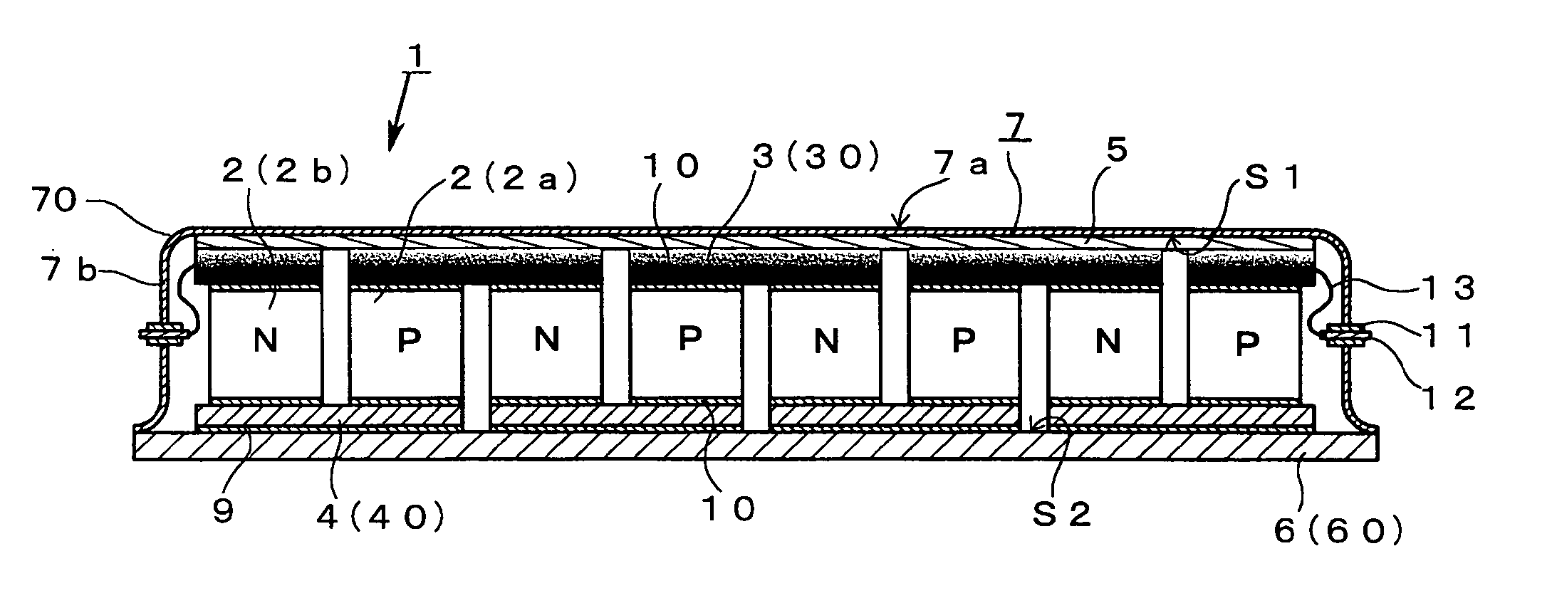
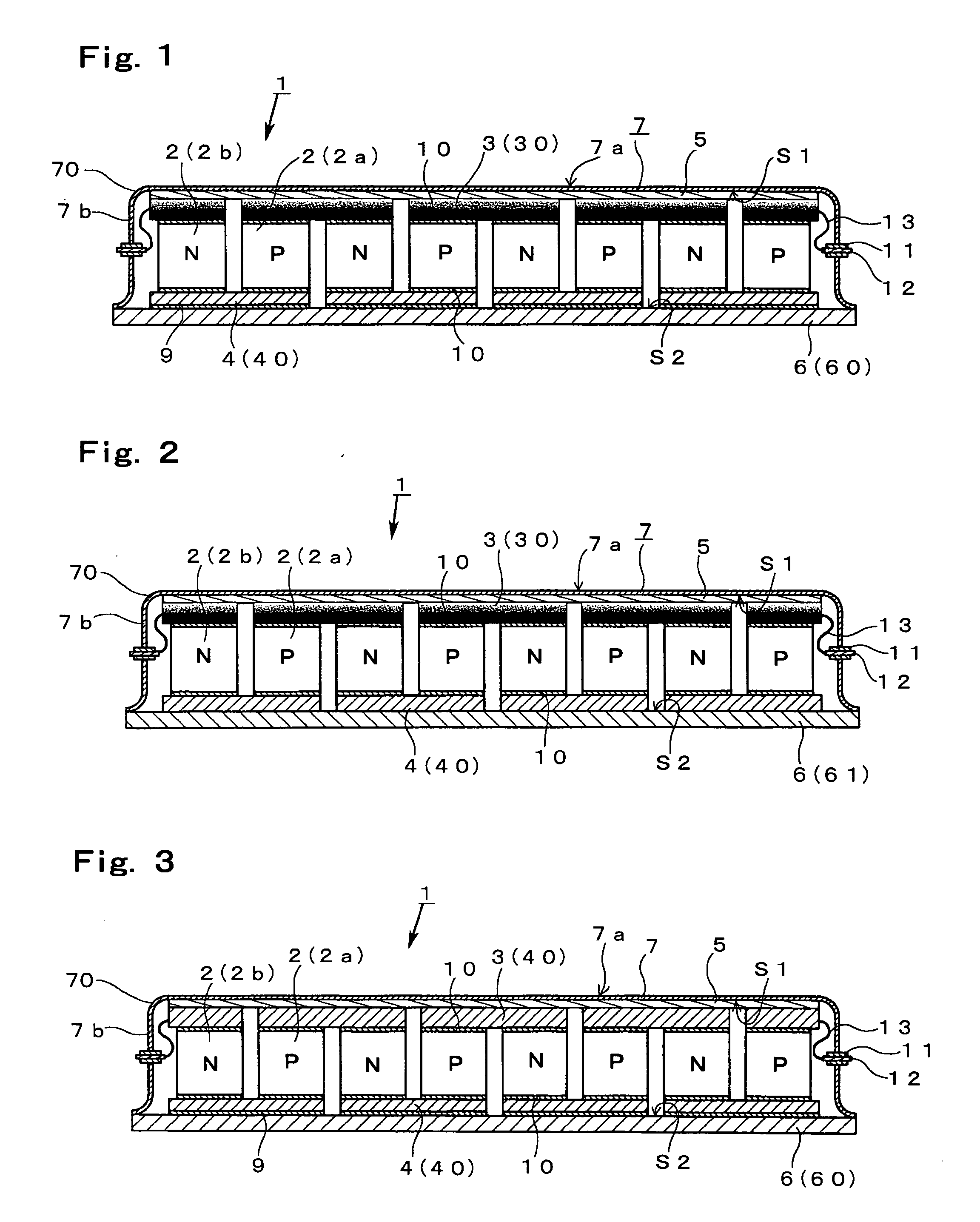
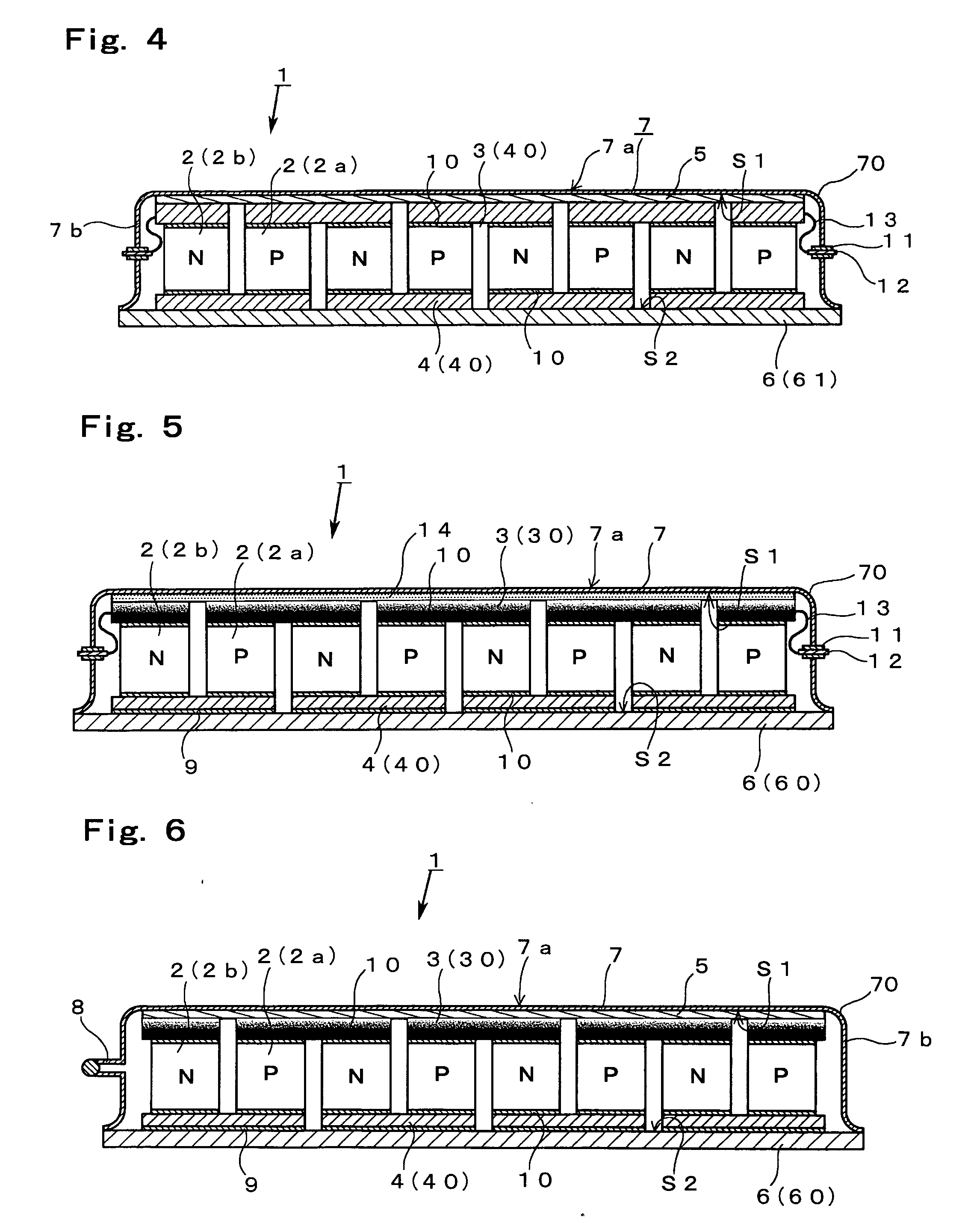
[0039] Hereunder, configurations of the present invention will be described in detail based on embodiments shown in the drawings.

[0040] FIGS. 1 to 9 show an embodiment of a thermoelectric conversion module according to the present invention. This thermoelectric conversion module 1 is a type for sealing thermoelectric semiconductors 2 in an airtight container 7, and includes at least a pair of thermoelectric semiconductors 2, a heat source side electrode portion 3 installed on a plane of a heat source side of the thermoelectric semiconductors 2 and electrically connected to the thermoelectric semiconductors 2, a radiation side electrode portion 4 installed on a plane of a low-temperature side of the thermoelectric semiconductors 2 on the opposite side to the heat source side electrode portion 3 and electrically connected to the thermoelectric semiconductors 2, a heating plate 7a and a cooling plate 6 for configuring a heat receiving portion by covering the electrode portions 3 and 4...


PUM


Abstract

A thermoelectric conversion module for generating power by using a temperature difference and realizing a large-size module with soundness to improve substantial filling density of a thermoelectric semiconductor, including a sliding member having high heat conductivity intervening at least between a heating plate of a high-temperature heat source side and a heat source side electrode portion of a thermoelectric semiconductor and a coupling plate for coupling the heating plate to the cooling plate, wherein the thermoelectric semiconductors and the electrode portions are integrated by being sandwiched between the cooling plate and the heating plate via the sliding member, and the sliding member in the pressurized state accepts relative sliding between the sliding member and the heat source side electrode portion or the heating plate.

Description

BACKGROUND OF THE INVENTION [0001] 1. Field of the Invention [0002] The present invention relates to a thermoelectric conversion module used for a thermoelectric conversion system of which heat source is waste heat of various kinds of industrial equipment and automobiles for instance. To describe it further in detail, the present invention relates to a technique for upsizing the thermoelectric conversion module. [0003] 2. Description of the Related Art [0004] As shown in FIG. 16, a conventional thermoelectric conversion module has a general configuration in which an electrical circuit is configured by providing electrodes 102 on top and under surfaces of multiple pairs of thermoelectric semiconductors 101, and an electrical insulating plate 103 such as a ceramics plate or a metal plate having an electrical insulating film are further provided outside each electrode. The multiple pairs of thermoelectric semiconductors 101 and the electrodes 102 are joined by a jointing material such ...

Claims


Application Information

Patent Timeline
Patent Type & Authority Applications(United States)
IPC IPC(8): H01L35/28
CPCH01L35/30H10N10/13
Inventor KAMBE, MITSURUSHIKATA, HIDEO
Owner CENTRAL RESEARCH INSTITUTE OF ELECTRIC POWER INDUSTRY
Why Eureka
Try Eureka