Method for extracting coal bed methane with source fluid injection

a technology of source fluid and methane, which is applied in the direction of directional drilling, chemistry apparatus and processes, and well accessories. it can solve the problems of increasing the cost of drilling operations, environmental difficulties in the handling and disposal of high-pressure underground hydrocarbon deposits, and limited success of high-pressure hydrocarbon deposits

Inactive Publication Date: 2006-01-12
WEATHERFORD TECH HLDG LLC
View PDF36 Cites 39 Cited by
  • Summary
  • Abstract
  • Description
  • Claims
  • Application Information

AI Technical Summary

Benefits of technology

[0019] In a third aspect, a method for drilling a lateral wellbore from a main wellbore is provided, comprising: a step for drilling the lateral wellbore from the main wellbore t

Problems solved by technology

However, due to the potential danger of a blowout in high pressure wells, in most instances an overbalanced situation is desired where the hydrostatic head of the drilling mud exceeds the underground hydrocarbon pressure by a predetermined safety factor.
Unfortunately, such prior systems that employ high density drilling muds to counterbalance the effects of high pressure underground hydrocarbon deposits have met with only limited success.
In order to create a sufficient hydrostatic head in many instances the density of the drilling muds has to be relatively high (for example from 15 to 25 pounds per gallon) necessitating the use of costly density enhancing additives.
Such additives not only significantly increase the cost of the drilling operations, but can also present environmental difficulties in terms of their handling and disposal.
High density muds are also generally not compatible with many 4-phase surface separation systems that are designed to separate gases, liquids and solids.
High density drilling muds also present an increased potential for plugging downhole components, particularly where the drilling operation is unintentionally suspended due to mechanical failure.
Further, the expense associated with costly high density muds is often increased through their loss into the underground

Method used


Image

  • Method for extracting coal bed methane with source fluid injection
  • Method for extracting coal bed methane with source fluid injection
  • Method for extracting coal bed methane with source fluid injection

Examples


Embodiment Construction

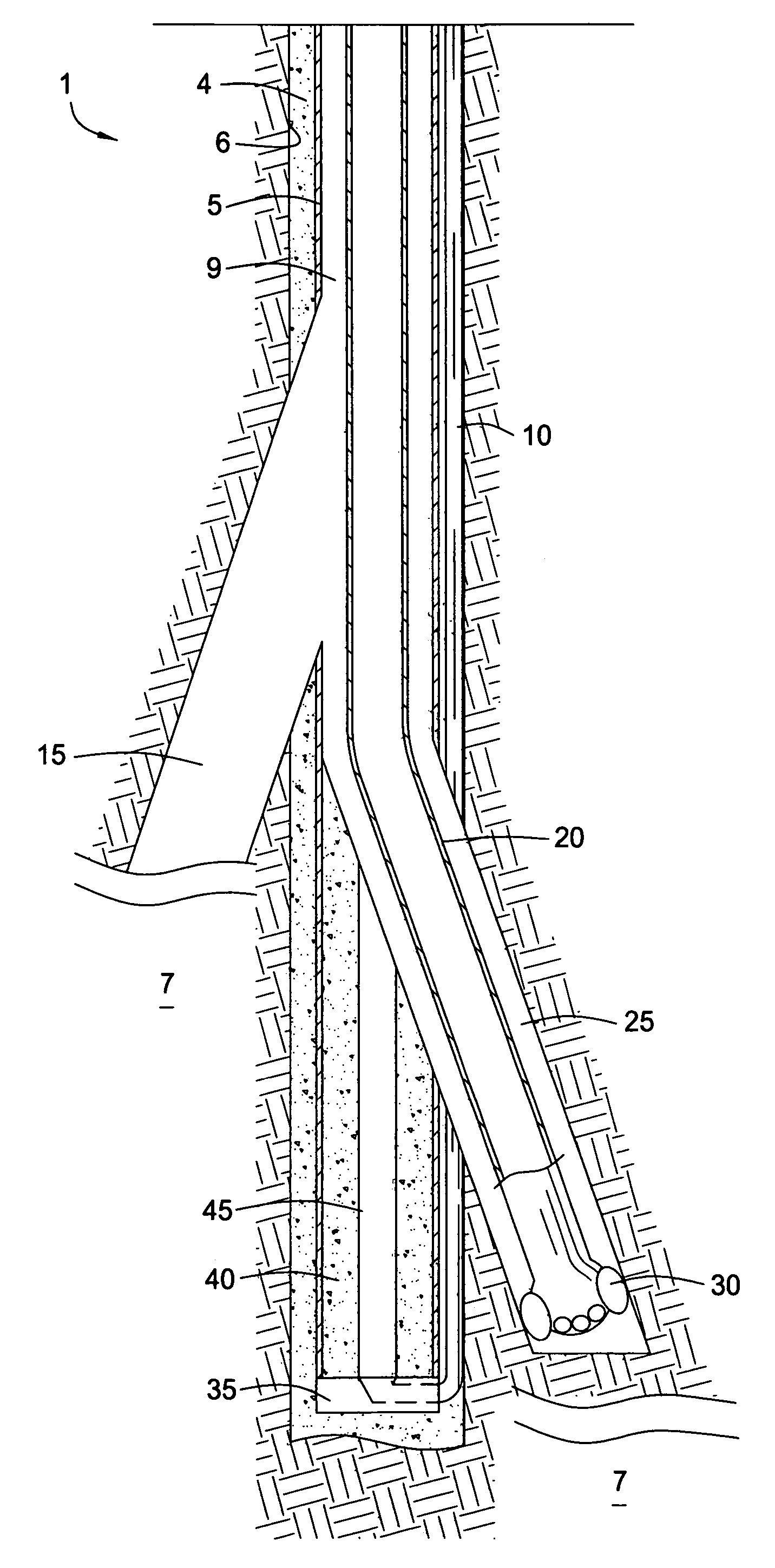
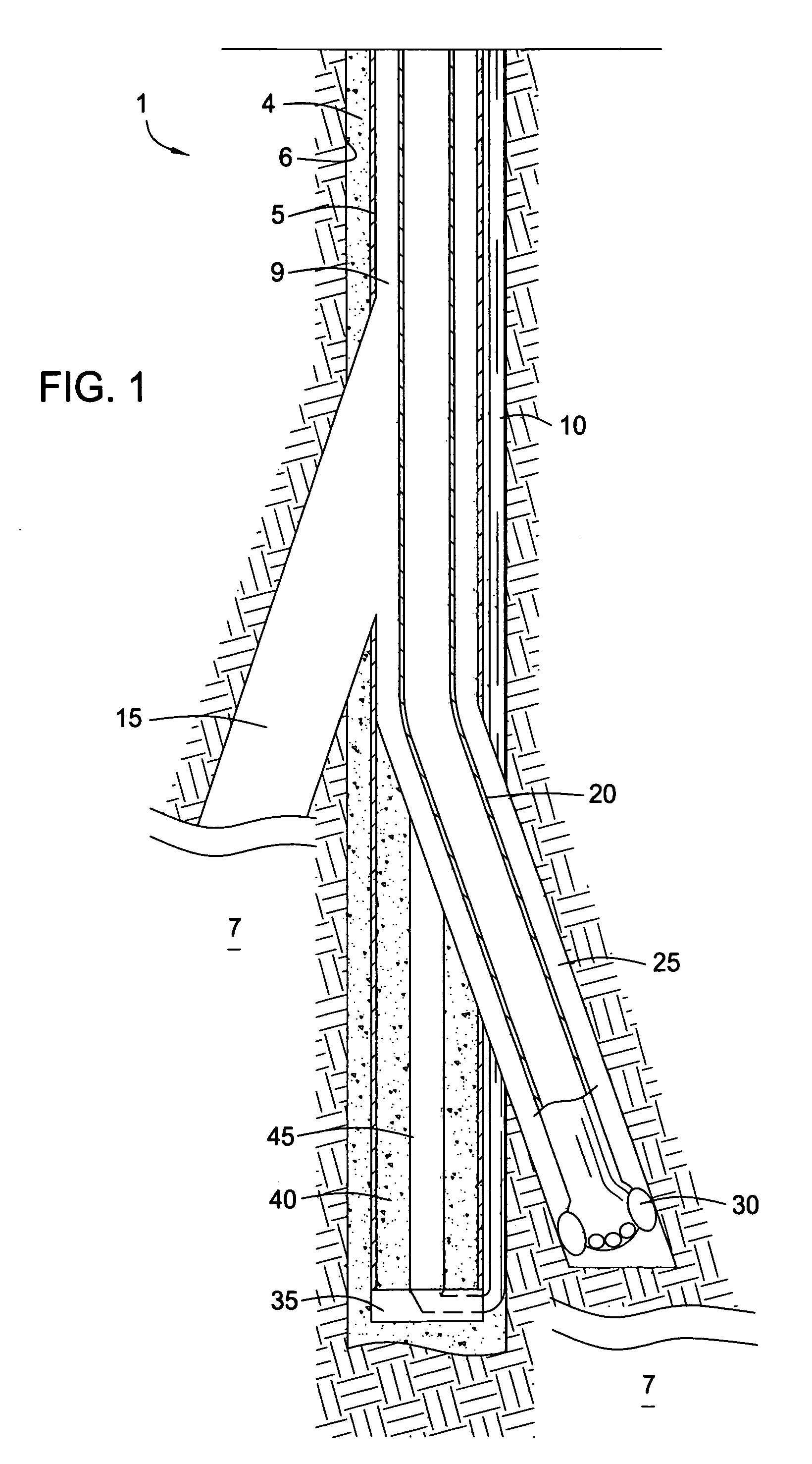
[0026] In the description that follows, like parts are marked throughout the specification and drawings with the same reference numerals. FIG. 1 is a sectional view of a multilateral well 1 showing a portion of a drilled lateral wellbore 15 and a second lateral wellbore 25 in the process of being drilled with a drilling technique according to one aspect of the present invention. The well 1 shown in FIG. 1 may be created in the following manner. A main wellbore 6 is drilled from the surface (not shown) below a starting depth of the deepest planned lateral wellbore, in this case lateral 25. Numeral 7 represents a formation of interest. Preferably, the formation 7 is a coal bed methane formation. However, the formation 7 may be any hydrocarbon bearing formation.

[0027] In one sub-aspect, before run in of casing 5, a pre-formed drillable plug 40 is attached to a top side of a diffuser shoe 35, preferably, with a threaded connection (not shown). Alternatively, the plug 40 may just rest o...


PUM


Abstract

The present invention generally provides an inexpensive method for drilling a multilateral wellbore where the pressure exerted on a formation of interest by a column of drilling fluid may be controlled. In one aspect, a method for drilling a lateral wellbore from a main wellbore is provided, including running a string of casing with an injection line connected thereto into the main wellbore, wherein the injection line is disposed along an outer side of the casing and a portion of the casing corresponding to a starting depth of the lateral wellbore is made from a drillable material; running a drillstring through the casing to the starting depth of the lateral wellbore, wherein the drillstring comprises a drill bit; injecting drilling fluid through the drill sting; and injecting a second fluid, having a density less than that of the drilling fluid, through the injection line at a rate corresponding to an injection rate of the drilling fluid to control hydrostatic pressure exerted by a column of the drilling fluid and the second fluid returning through the casing.

Description

BACKGROUND OF THE INVENTION [0001] 1. Field of the Invention [0002] Embodiments of the present invention generally relate to methods for extracting coal bed methane with source fluid injection. Specifically, methods are provided for forming one or more laterals off a main wellbore using an approach that is economical and does not substantially damage the formation. [0003] 2. Description of the Related Art [0004] A common method of drilling wells from the surface through underground formations employs the use of a drill bit that is rotated by means of a downhole motor (sometimes referred to as a mud motor), through rotation of a drill string from the surface, or through a combination of both surface and downhole drive means. Where a downhole motor is utilized, typically energy is transferred from the surface to the downhole motor through pumping a drilling fluid or “mud” down through a drill string and channeling the fluid through the motor in order to cause the rotor of the downhole...

Claims


Application Information

Patent Timeline
IPC IPC(8): E21B7/04E21B21/00E21B41/00E21B43/00
CPCE21B41/0035E21B2021/006E21B43/006E21B21/085
Inventor TERRY, JIMBAILEY, TOMVUYK, ADRIANCOY, ALEJANDRODIVINE, RONJOHNSON, DARRELL
Owner WEATHERFORD TECH HLDG LLC
Why Eureka
Try Eureka