Conical housing

a technology of diodes and housings, applied in sustainable buildings, lighting and heating apparatus, energy-efficient heating/cooling, etc., can solve the problems of weakening the hermetic seal and difficult manufacturing

Inactive Publication Date: 2006-01-12
COX ISAIAH WATAS
View PDF99 Cites 9 Cited by
  • Summary
  • Abstract
  • Description
  • Claims
  • Application Information

AI Technical Summary

Benefits of technology

[0016] A further advantage of the present invention is that diode devices having a conical housing are be able to function over a wider range of temperatures than previous devices, and will be able to be constructed from a wider range of materials.
[0017] A further advantage of the present invention is that a wider range of materials may be used in the construction of diode devices.
[0018] A further significant advantage of this design is that several packaging steps that were needed in previous approaches, such as introducing liquid metal, can be eliminated. The actuator is simply electrically and thermally bonded to the composite, substrate or electrode pair precursor.
[0019] For a more complete understanding of the present invention and the technical advantages thereof, reference is made to the following description taken with the accompanying drawings, in which:
[0020]FIG. 1 is a cross sectional view of a prior art modified electrode;
[0021]FIG. 2 is a diagrammatic representation of one embodiment of a prior art tubular housing / actuator;

Problems solved by technology

One drawback is that the device must contain some 106 elements in order to provide reasonable efficiency, and this is difficult to manufacture.
A further drawback results from the losses due to thermal conduction: although the oxide spacers have a small contact coefficient with the emitter and collector elements, which minimizes thermal conduction, the number of elements required for the operation of the device means that thermal conduction is not insignificant.
However, during operation, The thermal environment of the two electrodes will be dissimilar—one will be hotter relative to the other—and their differential expansion will put a strain on the join between the electrodes and the housing, thereby weakening the hermetic seal.

Method used


Image

  • Conical housing
  • Conical housing
  • Conical housing

Examples


second embodiment

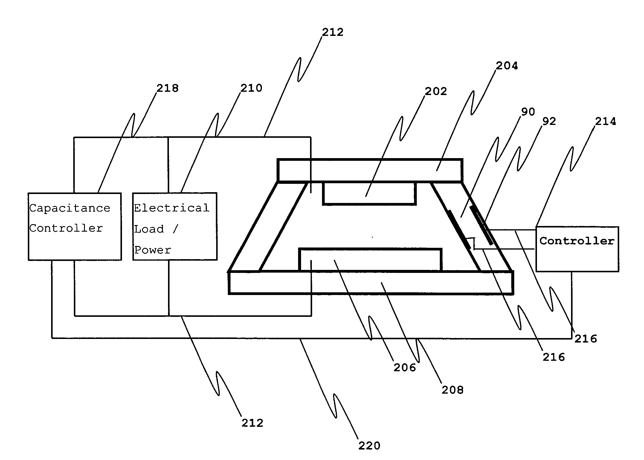
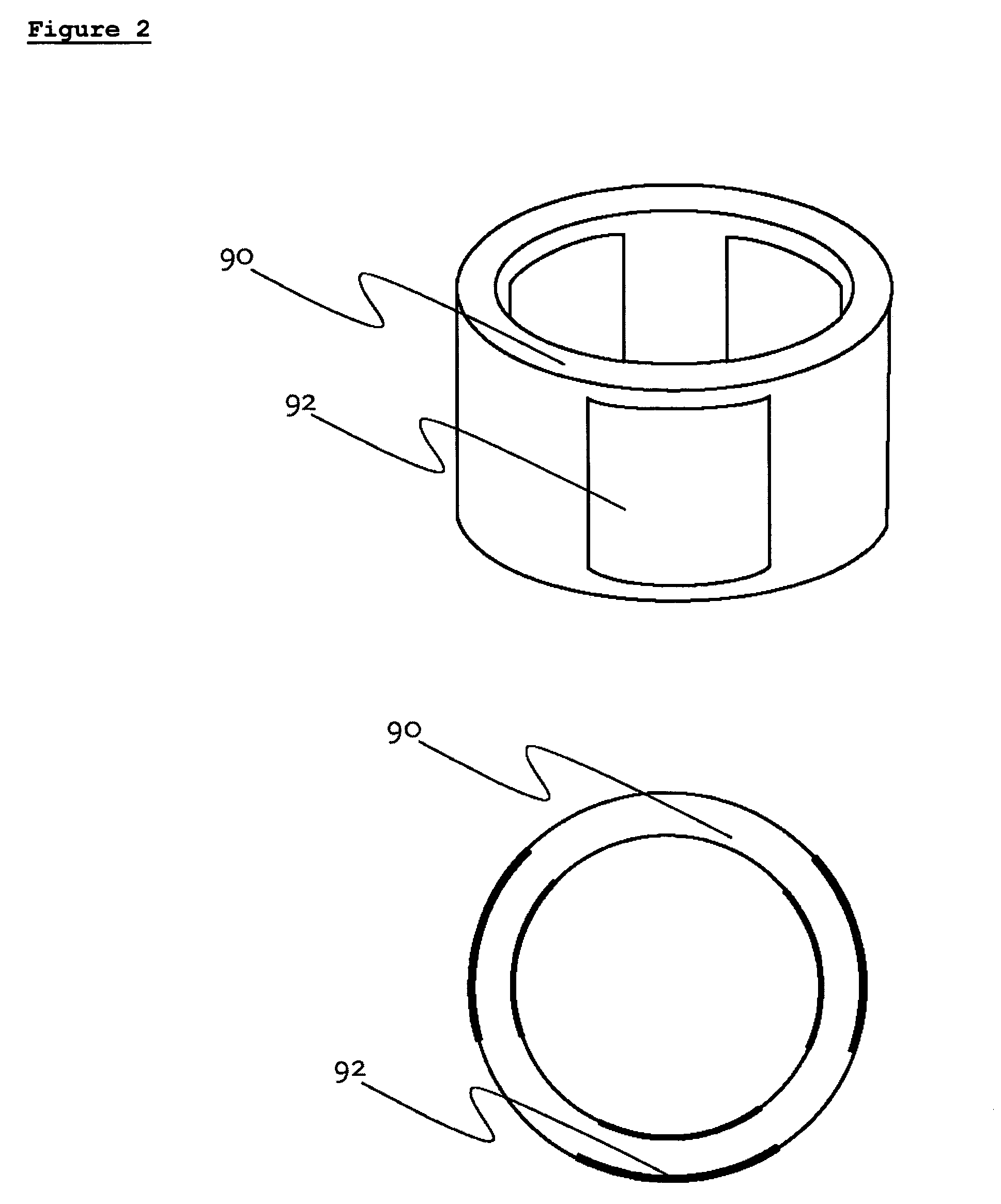
[0032] For example, U.S. Pat. No. 6,720,704 discloses diode devices in which the separation of the electrodes is set and controlled using piezo-electric, electrostrictive or magnetostrictive actuators. Thus in the present invention, the conical housing is formed from piezo-electric, electrostrictive or magnetostrictive actuators. In this embodiment, the conicalhousing comprises actuators, such that a conical diode device is formed. This embodiment is illustrated in FIG. 5, which shows a diode device 80, in which two electrodes 82 and 86 are separated by a conical piezo actuator 84. Piezo actuator 84 is used to control the distance between electrodes 82 and 86. A more detailed representation may be obtained by referring to FIG. 6, which shows in a diagrammatic form a diode device of the present invention, a first electrode 202, disposed on substrate 204, is attached to the end of actuator cone 90, and a second electrode 206, disposed on substrate 208, is attached to the other end of ...

third embodiment

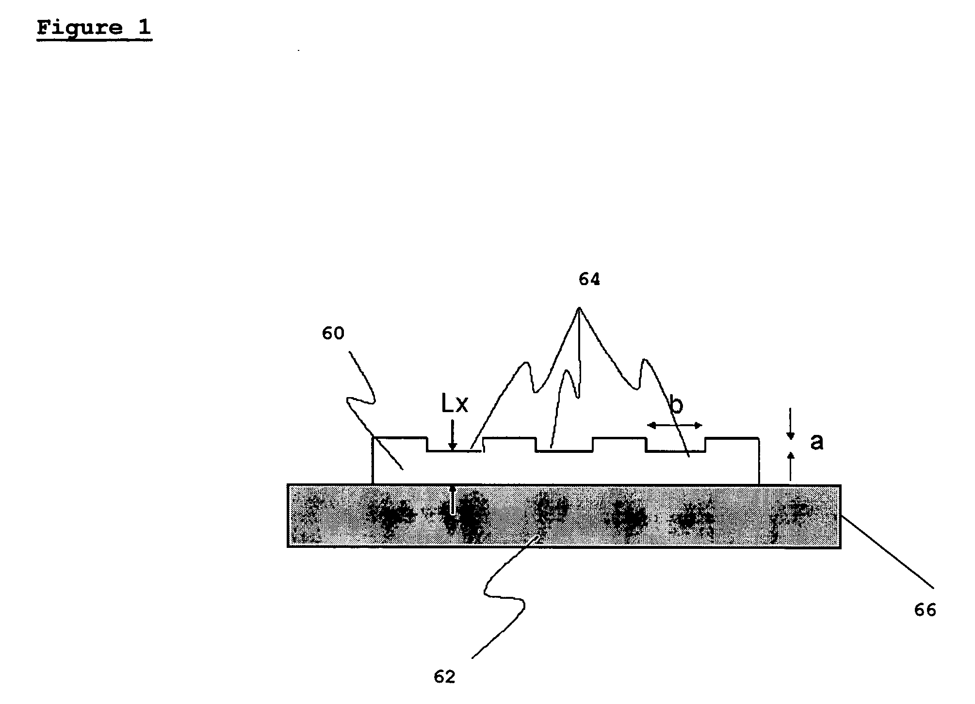
[0039] The electrodes utilized in the present invention may be formed from materials disclosed in diode device configurations of the prior art. For example, electrodes disclosed in Patent Number WO03 / 090245 may be utilized with relatively little modification. For example, a typical diode device may be constructed with electrodes made from copper and silicon, which are of different sizes even in previous models. This design further has the added benefits of a long heat flow path and a long piezo distance to provide a lot of throw, without greatly modifying the previous design. Furthermore, in a third embodiment, the diode device of the present invention is built with the modified electrode disclosed in WO03 / 083177 and shown in FIG. 1, which allows for a decrease in the work function of the electrode, and therefore an increase in the efficiency of the device. It is to be understood that the modified electrode 66 may be used as one or both electrodes in the diode device of the present ...


PUM


Abstract

A conical diode device is disclosed, comprising a pair of electrodes and a conical housing. The conical housing ensures that the hermetic seal between the electrodes and the housing remains strong despite thermal imbalances between the two electrodes when the device is in operation. In one embodiment, the conical housing additionally serves as a means for controlling the separation between the electrode pair. In a preferred embodiment, the conical actuating element is a quartz piezo-electric cone. In another embodiment, a modified electrode for use in a diode device of the present invention is disclosed, in which indents are made on the surface of the electrode.

Description

CROSS-REFERENCE TO RELATED APPLICATIONS [0001] This application claims the benefit of U.K. Provisional Application No. GB0415426.6, filed Jul. 9, 2004. BACKGROUND OF THE INVENTION [0002] The present invention relates to diode devices, particularly diode devices for heat pumping or energy conservation. [0003] In U.S. Pat. No. 6,720,704 diode devices are disclosed in which the separation of the electrodes is set and controlled using piezo-electric, electrostrictive or magnetostrictive actuators. This avoids problems associated with electrode spacing changing or distorting as a result of heat stress. In addition it allows the operation of these devices at electrode separations which permit quantum electron tunneling between them. Pairs of electrodes whose surfaces replicate each other are also disclosed. These may be used in constructing devices with very close electrode spacings. [0004] In U.S. Pat. No. 6,417,060 a method for manufacturing a pair of electrodes is disclosed which compr...

Claims


Application Information

Patent Timeline
Patent Type & Authority Applications(United States)
IPC IPC(8): H01L23/06F25B21/00H01J21/04
CPCF25B21/00F25B2321/003Y02B30/66H01J21/04F25B2500/01Y02B30/00
Inventor COX, ISAIAH WATAS
Owner COX ISAIAH WATAS
Why Eureka
Try Eureka