AC motor and control device therefor

a control device and motor technology, applied in the direction of dynamo-electric converter control, magnetic circuit rotating parts, shape/form/construction, etc., can solve the problems of excessive torque ripples or vibrations, noise, and deterioration of the driving efficiency of transistors, and achieve low cost, increase torque generation, and small size

Inactive Publication Date: 2006-01-12
DENSO CORP
View PDF11 Cites 49 Cited by
  • Summary
  • Abstract
  • Description
  • Claims
  • Application Information

AI Technical Summary

Benefits of technology

[0009] The present invention has been made in view of such circumstances, and has as its object to provide an AC motor of smaller size and low costs, which can increase generation of torque, and to provide a control device therefor.

Problems solved by technology

There has also been a problem that leakage of the magnetic flux between the stator poles of the P phase and those of the Q phase causes excessive torque ripples or vibration, and noises.
Further, in controlling the voltage and current of a two-phase motor by a transistor inverter, unlike three-phase AC control which requires six transistors for parallel three-phase control, more number of transistors, such as eight, is required to thereby induce problematic deterioration in the driving efficiency of transistors and induce complexity in control.

Method used


Image

  • AC motor and control device therefor
  • AC motor and control device therefor
  • AC motor and control device therefor

Examples


first modification

[0121] (First Modification)

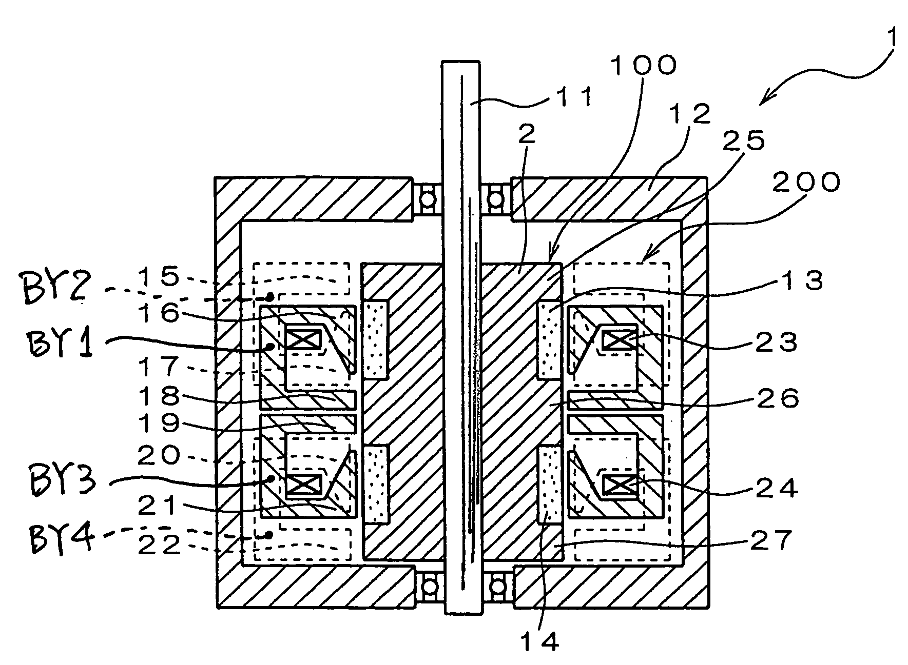
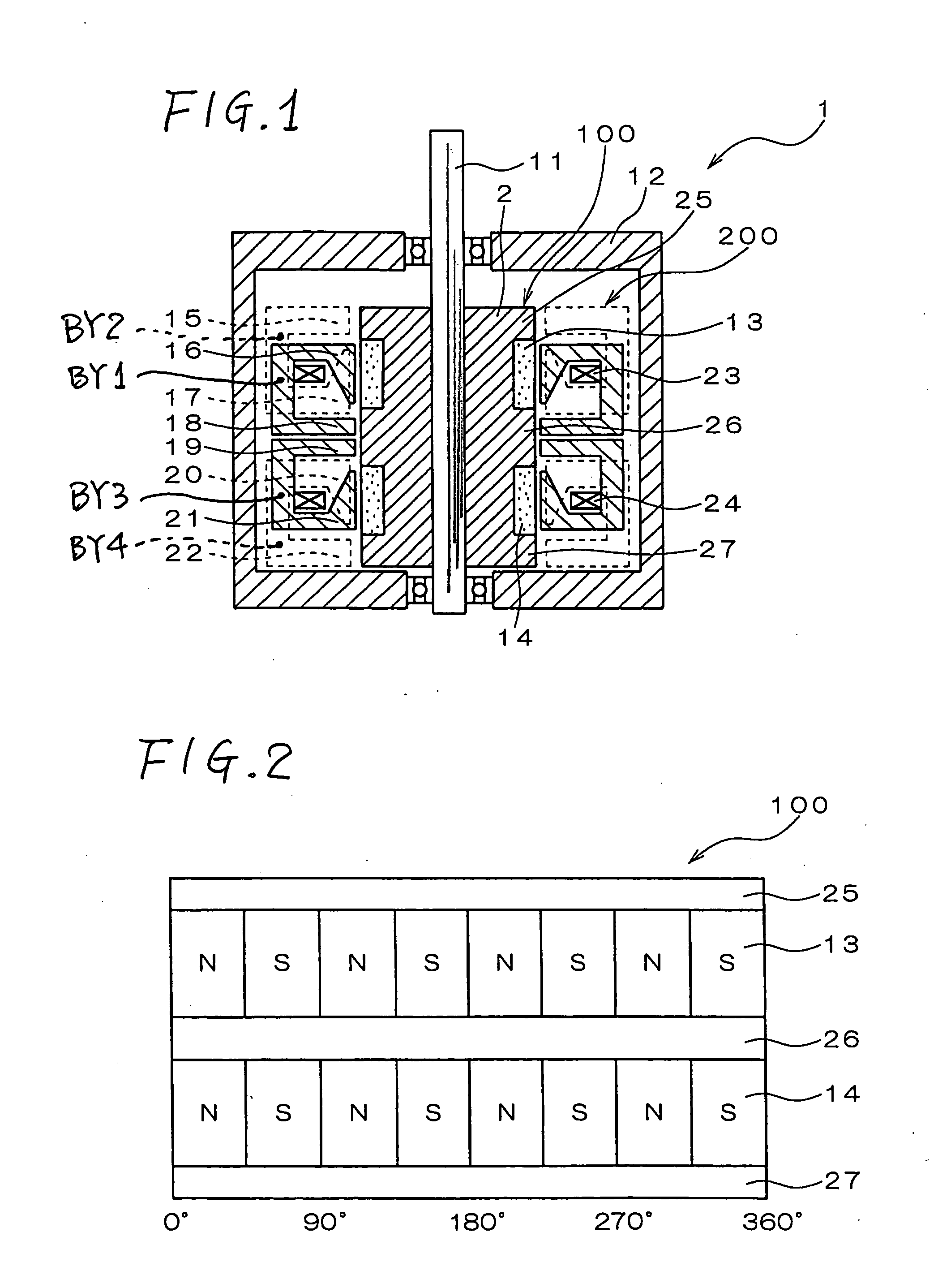
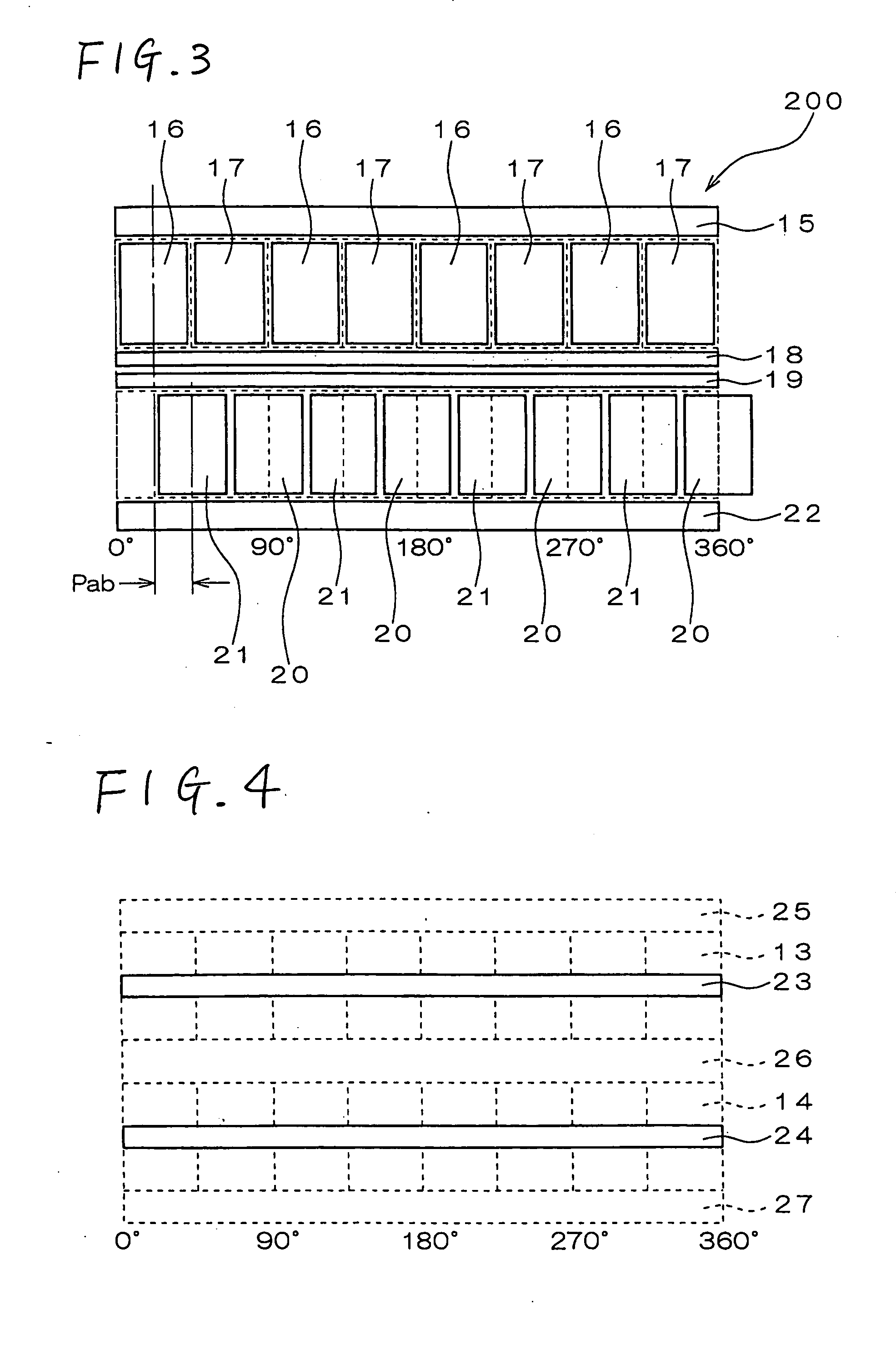
[0122]FIG. 17 is a vertical cross section of a modification of the AC motor, in which the shapes of the stator poles and the stator-side neutral poles are improved. In the AC motor 1 shown in FIG. 1, the stator poles and the stator-side neutral poles of the individual phases are located so that the magnetic circuits extending from the outer periphery of the stator to the air gap between the stator 200 and the rotor 100 are formed at different positions in the direction along the rotor shaft 11. Therefore, the length of the motor is so much the larger. Contrarily, in the modified AC motor shown in FIG. 17, the magnetic circuits extending from the outermost diameter of the stator having P-phase stator poles 37 and a P-phase stator-side neutral pole 38 to the air gap, are formed at the same position in the axial direction of the rotor. In short, the magnetic circuits are formed on the same circumference so that the length along the rotor shaft 11 may be so mu...

second modification

[0124] (Second Modification)

[0125] Two-phase AC motors, each consisting of a P phase and a Q phase, have been described with reference to FIGS. 1 to 21. The similar concept may be applied to an N-phase AC motor (N is more than 2) by providing the N number of modules (actuators) for the respective phases.

[0126] Specifically, the structure illustrated in FIG. 1 includes two-phase AC motor, and thus the motor includes two actuators whose phase difference is 90 degrees. In this regard, by providing the N number of actuators in the axial direction and by relatively offsetting the phases from each other by 360 / N degrees in electrical angle, an N-phase AC motor may be structured.

[0127] As shown in FIG. 17, in case a composite construction part of which is made composite, the composite components may be serially arranged in the axial direction, while offsetting the phases by the electrical angle of 360 / N, whereby an N-phase AC motor may be constituted. In this connection, however, the str...

third modification

[0128] (Third Modification)

[0129] In the AC motor described above referring such as to FIG. 1, a principal torque constant, i.e. an output torque which is obtained by passing the same current through the same winding, may be increased by multipolarization. However, the multipolarization arises a problem that the distance between the individual stator poles is shortened to thereby increase leakage flux from between the individual stator poles. Such an increase in the leakage flux between poles causes reduction of flux which is effective in generating torque, thereby reducing generation of torque and reducing power factors, and thus ultimately reducing efficiency. The increase also causes excessive torque ripples, vibration or noise.

[0130] FIGS. 22 to 25 show transverse cross sections of an AC motor for reducing leakage flux between stator poles. These figures illustrate a structure in which the number of poles is increased to 16. FIGS. 22 to 25 show, respectively, the configurations...


PUM


Abstract

A rotor, which is rotatable about a rotor shaft, comprises N poles and S poles alternately disposed in the circumferential direction, and rotor-side neutral poles disposed adjacent to the N poles and the S poles along the axial direction of the rotor, being magnetically connected to their back yoke. A stator comprises two modules which are adjacently disposed in the axial direction of the rotor. Each of these two modules comprises a winding wound, in a loop shape, around the rotor shaft, stator-side neutral poles disposed at positions opposed to the rotor-side neutral poles, stator poles each of which is disposed at a position opposed to either the N pole or the S pole, and a back yoke which connects the stator-side neutral poles and the stator poles to surround the winding.

Description

CROSS-REFERENCE TO RELATED APPLICATION [0001] This application is based on and claims the benefit of priority from earlier Japanese Patent Application No. 2004-202579 filed on Jul. 9, 2004, the description of which is incorporated herein by reference. BACKGROUND OF THE INVENTION [0002] 1. Field of the Invention [0003] This invention relates to an AC motor, such as a stepping motor which is rotated and driven by polyphase current, and to a control device therefor. [0004] 2. Related Art [0005] Conventionally, stepping motors are known which are rotated and driven by using two phase currents of a P phase and a Q phase as disclosed in Japanese Published Unexamined Patent Application No. 2001-161055. FIG. 51 is a cross section showing a configuration of a conventional two-phase stepping motor in case of eight poles. FIG. 52 is a circumferential expansion plan of a permanent magnet provided in a rotor of the two-phase stepping motor shown in FIG. 51. FIG. 53 is a circumferential expansion...

Claims


Application Information

Patent Timeline
Patent Type & Authority Applications(United States)
IPC IPC(8): H02K37/00H02K1/14H02K1/27H02K3/28H02K21/14H02K37/14H02P8/12
CPCH02K1/145H02K37/14H02K1/278H02K1/2781
Inventor NASHIKI, MASAYUKI
Owner DENSO CORP
Why Eureka
Try Eureka