Eureka AIR delivers breakthrough ideas for toughest innovation challenges, trusted by R&D personnel around the world.

Liquid crystal display and backlight adjusting method

Active Publication Date: 2006-01-12
SATURN LICENSING LLC
View PDF16 Cites 62 Cited by
  • Summary
  • Abstract
  • Description
  • Claims
  • Application Information

AI Technical Summary

Benefits of technology

[0008] The present invention provides in an embodiment a thin type liquid crystal display apparatus and a backlight adjustment method that do not need the user to adjust the luminance of the backlight and that can be adjusted with high accuracy.
[0011] a control circuit that generates a drive signal that keeps the luminance of the backlight almost constant on the basis of a detection signal detected by the luminance sensor.
[0015] According to this aspect in an embodiment, since luminance sensors and pixel transistors of the LCD are formed in the same process, a thin type LCD panel unit can be produced. In addition, the luminance of the backlight can be kept constant.
[0018] The liquid crystal display apparatus according to an embodiment the present invention can keep the luminance of the backlight constant even if the aged deterioration takes place in the liquid crystal display apparatus.
[0019] According to the present invention in an embodiment, the luminance detection means of the backlight can be disposed on the substrate for the pixel transistors of the LCD. In addition, the luminance detection means can be formed in the process for the pixel transistors. Thus, the cost of the sensors can be decreased. In addition, since the sensors can be formed in the LCD module, it can be thinned.

Problems solved by technology

However, the luminance of the backlight of the LCD module described in the document deteriorates by aged deterioration or the like.
Thus, after the liquid crystal display had been shipped, the aged deterioration of the luminance of the backlight could not be handled or it was improperly adjusted.

Method used


Image

  • Liquid crystal display and backlight adjusting method
  • Liquid crystal display and backlight adjusting method
  • Liquid crystal display and backlight adjusting method

Examples


Embodiment Construction

[0037] The present invention relates to a liquid crystal display apparatus and a backlight adjustment method.

[0038] Next, with reference to the accompanying drawings, an embodiments of the present invention will be described. Before that, a typical structure of a liquid crystal display apparatus will be described.

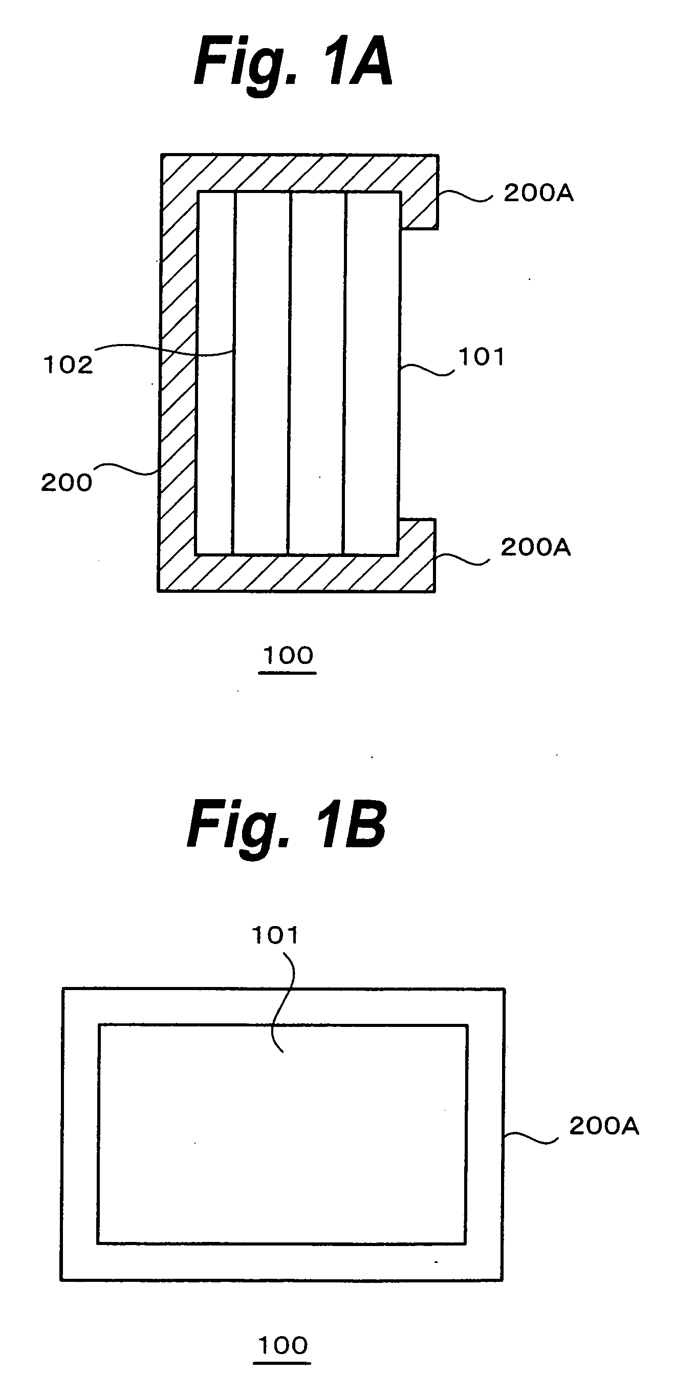
[0039] As shown in FIG. 1A and FIG. 1B, a liquid crystal display apparatus 100 is composed of an LCD panel unit 101 and a backlight unit 102. In addition, a circuit for a control system is also disposed in the liquid crystal display apparatus 100. These units are housed in a housing 200. Reference numeral 200A represents a frame portion that surrounds a screen of the housing 200.

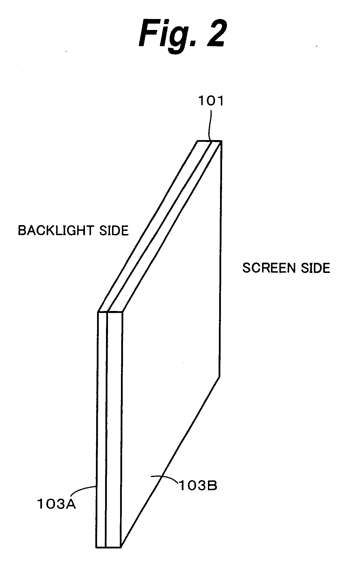
[0040] As shown in FIG. 2, the LCD panel unit 101 is composed of two substrates 103A and 103B that are layered. The LCD panel unit 101 is a thin film transistor (TFT) liquid crystal. The TFT is categorized as an amorphous silicon type and a polysilicon type. The amorphous silicon type uses an amo...


PUM


Abstract

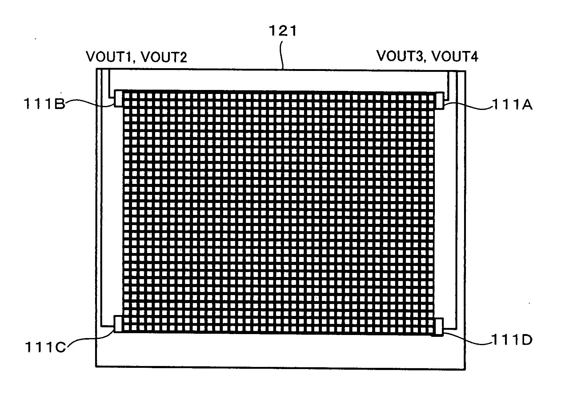
A liquid crystal display apparatus and backlight adjustment method are provided. Backlight luminance sensors 111A to 111D are disposed in the vicinity of four outer corners of an effective screen of an LCD panel 121. Each of the backlight luminance sensors 111A to 111D detects the luminance of each of three primary colors. A backlight unit is composed of a three-primary LED array and a light diffusion unit. Transistors of the backlight luminance sensors and transistors of a pixel portion are formed on the same substrate in the same process. When a transistor is irradiated with backlight in its sufficient off region, an off current occurs due to light excitation. Since the value of the off current corresponds to the luminance of the rays of backlight that irradiates the transistor, the luminance of the backlight is detected with an output voltage into which the off current is converted. As a result, the luminance of the backlight is kept constant.

Description

CROSS REFERENCE TO RELATED APPLICATION [0001] The present application claims priority to Japanese Patent Document No. P2003-408735 filed on Dec. 8, 2003, the disclosure of which is herein incorporated by reference. BACKGROUND OF THE INVENTION [0002] The present invention relates to a liquid crystal display apparatus and a backlight adjustment method. [0003] A liquid crystal display (hereinafter abbreviated as an LCD), which is of non-self emitting type, needs backlight as a light source. Examples of the backlight are a cold cathode ray tube and a light emitting diode (hereinafter abbreviated as an LED). When an LED is used, a white diode can be used. However, in a liquid crystal television monitor, three-primary color LEDs of R (red), G (green), and B (blue) are often used to improve color reproducibility. By mixing these colors of these LEDs, white backlight is formed. [0004] When a white LED is used for backlight, since the luminance and chromaticity of the backlight depend on the...

Claims


Application Information

Patent Timeline
IPC IPC(8): G09G3/36G02F1/13357G02F1/1362G09G3/34
CPCG02F1/133603G02F1/1362G09G3/3413G09G3/3648G09G2320/0626G09G2320/0666
Inventor ICHIKAWA, HIROAKI
Owner SATURN LICENSING LLC
Why Eureka
Eureka Blog
Learn More