Packet communicating apparatus

a communication apparatus and packet technology, applied in the field of packet communication apparatus, can solve the problems of discarded and not used in the rlc protocol process, and achieve the effect of improving transmission efficiency, and effectively using the padding area

Inactive Publication Date: 2006-01-12
FUJITSU LTD
View PDF11 Cites 33 Cited by
  • Summary
  • Abstract
  • Description
  • Claims
  • Application Information

AI Technical Summary

Benefits of technology

[0030] Also, there is a method of effectively using the padding area by jointly putting STATUS-PDU for transmission confirmation as PIGGYBACK-STATUS, on the padding area (FIG. 16B). However, the high speed packet communication has a tendency that a WINDOW size indicating a transmittable PDU number without any transmission confirmation is enlarged to drop the transmission frequency of STATUS-PDU and improve the transmission efficiency. Thus, the padding area may not be effectively used in PIGGYBACK-STATUS (FIG. 16B). In this way, the current system, although having means for effectively using the padding area, does not have a method of positively suppressing the occurrence of the padding area.
[0031] The present invention has been proposed in view of the circumstances. It is therefore an object of the present invention to provide a packet communicating apparatus that can reduce a padding area.

Problems solved by technology

However, the padding area is not finally used in the RLC protocol process and discarded in the RNC and the MS.

Method used


Image

  • Packet communicating apparatus
  • Packet communicating apparatus
  • Packet communicating apparatus

Examples


first embodiment

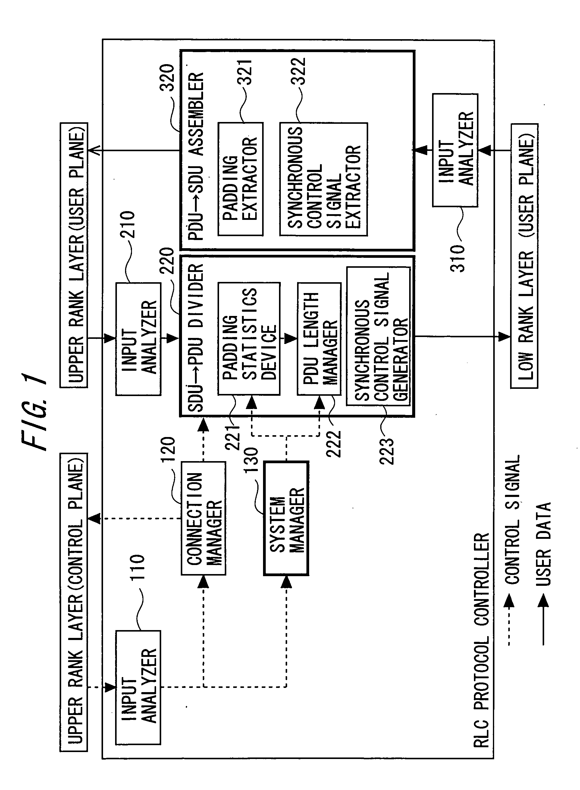
[0057] At first, the first embodiment of the packet communicating apparatus in the present invention is explained with reference to the drawings. FIG. 1 is a block diagram of an RLC protocol controller used in the first embodiment of the packet communicating apparatus in the present invention.

[0058] The RLC protocol controller shown in FIG. 1 includes an input analyzer 110, a connection manager 120, a system manager 130, an input analyzer 210, an SDU→PDU divider 220, an input analyzer 310, and a PDU→SDU assembler 320.

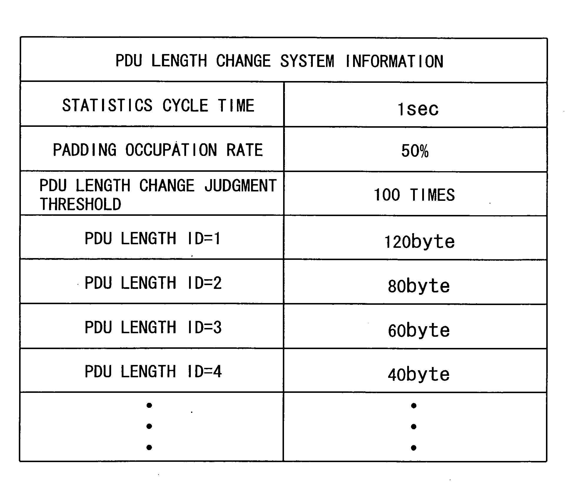
[0059] Also, the SDU→PDU divider 220 includes a padding statistics device 221, a PDU length manager 222, and a synchronous control signal generator 223. Also, the PDU SDU assembler 320 includes a padding extractor 321 and a synchronous control signal extractor 322.

[0060] The input analyzer 110 analyzes a signal received from an upper rank layer (control plane). The input analyzer 110, when receiving call control information, reports to the connection manager 120. Als...

second embodiment

[0106] The second embodiment of the packet communicating apparatus in the present invention will be described below with reference to FIGS. 1, 9, and 10. FIG. 10 is a flow chart showing the PDU→SDU assembling process in the second embodiment of the packet communicating apparatus in the present invention. Also, FIGS. 1 and 9 are the views to explain the first embodiment of the packet communicating apparatus in the present invention and also used to explain this embodiment.

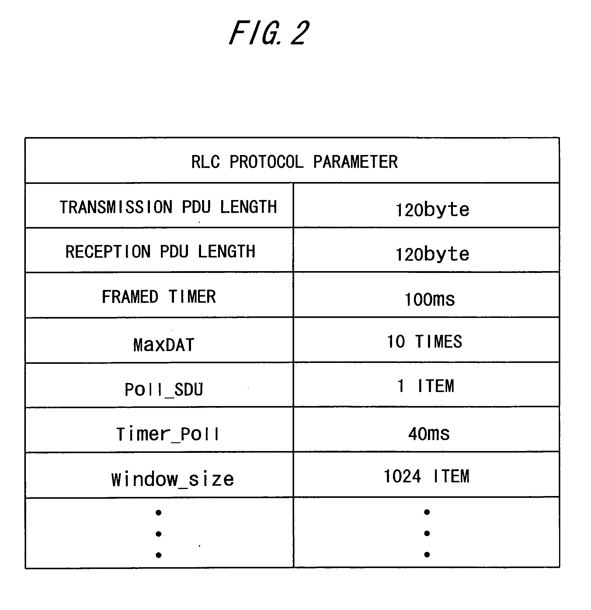
[0107] When receiving the PDU of 120 bytes from the user plane of the low rank layer of the U1, the PDU→SDU assembler 320 carries out the reception from the lead PDU to the final PDU and assembles the SDU.

[0108] Then, the PDU→SDU assembler 320 carries out a PDU analyzing process (S1001) and judges whether or not there is a padding area (S1002). For example, if the SDU of 1,040 bytes was assembled, the padding area exists in the final PDU. So, the PDU→SDU assembler 320 duplicates the final PDU and passes to the pad...


PUM


Abstract

To provide a packet communicating apparatus that can reduce a padding area. A packet communicating apparatus used in a high speed packet communication in a radio mobile communication network includes: an SDU→PDU divider for dividing packet data to be transmitted to an opposite entity, into protocol data units; and a synchronous control signal generator 223 for jointly putting a control signal to change a protocol data unit length, on a padding area of a protocol data unit occurring at a time of the division.

Description

BACKGROUND OF THE INVENTION [0001] 1. Field of the Invention [0002] The present invention relates to a packet communicating apparatus in a mobile radio network. [0003] 2. Description of Related Art [0004] A mobile network of W-CDMA (Wideband Code Division Multiple Access) is provided with a mobile station (MS), a radio base station (NodeB), a radio network controller (RNC), and a radio packet communication node (SGSN GGSN) (FIG. 11). FIG. 11 is a configuration view of a W-CDMA radio network system. [0005] The RNC and the MS each employ an RLC (Radio Link Control) protocol (3GPP Recommendation TS25.322), in order to effectively carry out a packet communication in a radio block. Then, each of the RNC and the MS has an RLC protocol controller to control the RLC protocol. The RLC protocol controllers of the RNC and the MS carry out the division of packet data at a time of data transmission. Also, the RLC protocol controllers of the RNC and the MS carry out the assembly to the packet dat...

Claims


Application Information

Patent Timeline
Patent Type & Authority Applications(United States)
IPC IPC(8): H04J3/22H04J3/16H04J3/24H04B7/00H04W28/00H04W28/06H04W72/04H04W76/02
CPCH04W28/06
Inventor OISHI, SHINJIKOGA, TSUNEAKITAKATA, TATSUHIKOOISHI, YUICHIRO
Owner FUJITSU LTD
Why Eureka
Try Eureka