Air damper

a damper and air technology, applied in the field of air dampers, can solve problems such as difficulty in controlling dimensional and shape, and achieve the effects of reducing idling distance, reducing gap, and suitably increasing strength

Active Publication Date: 2006-01-19
NIFCO INC +1
View PDF11 Cites 6 Cited by
  • Summary
  • Abstract
  • Description
  • Claims
  • Application Information

AI Technical Summary

Benefits of technology

[0011] In the present invention, the recess portion is provided on the side opposite to the piston rod in order to prevent sink in the piston made of a synthetic resin. The protruding portion is provided on the bottom of the cylinder, and protrudes into the recess portion when the piston moves into the cylinder to a maximum extent. In this state, air is not accumulated in the recess portion to a large extent. Accordingly, it is possible to reduce a idling distance (interval in which damper effect is not obtained) due to expansion of the air accumulated in the recess portion when the piston starts to move from the maximally plunged state. Therefore, the damper effect of the air damper can be obtained over substantially an entire stroke of the piston.
[0012] In the invention, the protruding portion may be formed in an arc or circular rib shape extending coaxially with the axis of the cylinder. Accordingly, the piston can respond to a case of rotating freely around the axis. The protruding portion may be formed in plural arc or circular rib shapes extending on plural concentric circles with respect to the axis of the cylinder. Accordingly, the piston can respond to a case of rotating freely around the axis. In addition, by providing plural ribs on the bottom part of the cylinder, the strength can be suitably increased.
[0013] In the invention, the protruding portion may be formed in a shape corresponding to that of the recess portion. Accordingly, it is possible to reduce a gap in which air is accumulated in a state in which the protruding portion moves into the recess portion, thereby reducing the idling distance.

Problems solved by technology

In this case, sink or deformation may occur, thereby making it difficult to control dimensional and a shape.

Method used


Image

  • Air damper
  • Air damper
  • Air damper

Examples


Embodiment Construction

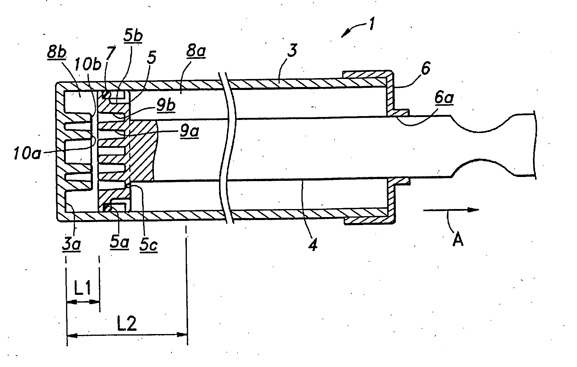
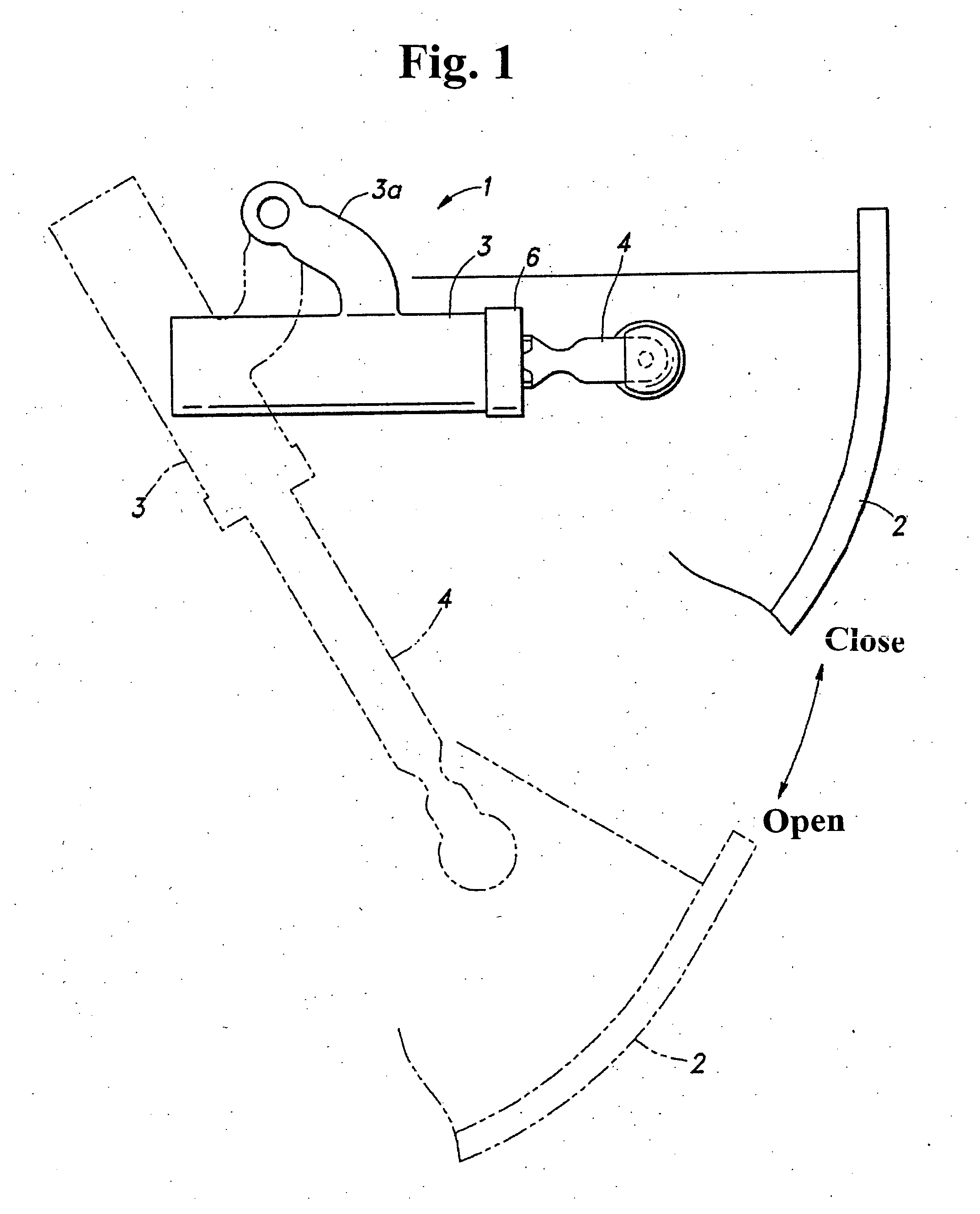
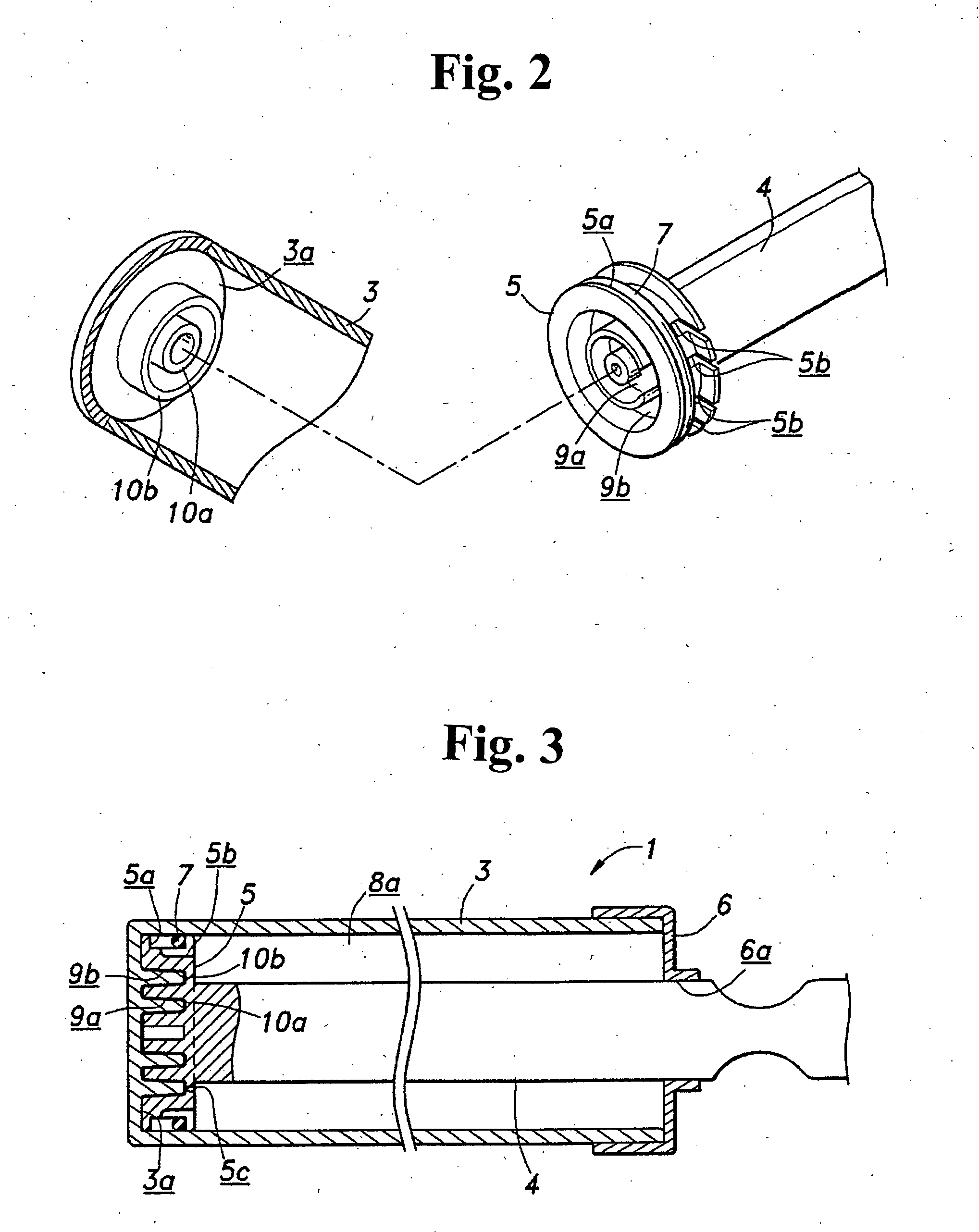
[0020] Hereunder, embodiments of the present invention will be explained with reference to the accompanying drawings. FIG. 1 is a side view showing essential components of an air damper 1 for an automobile glove compartment 2 according to an embodiment of the present invention. A cylinder 3 of the air damper 1 is pivotally supported by means of an integrally formed arm 3a on a dashboard (not shown). A front end part (protruding end part) of a piston rod 4 protruding out from the cylinder 3 is linked in a suitable place of the glove compartment 2. The piston rod 4 is plunged into the cylinder 3 in a fully closed state of the glove compartment 2 shown by solid lines in the drawing. The piston rod 4 is protruding out to the longest or near that in the fully open state shown by phantom lines in the drawing.

[0021] The air damper 1 is used for opening and closing the glove compartment 2. When the glove compartment 2 opens by its own weight, it opens gently by the damper effect, and when ...


PUM


Abstract

An air damper includes a cylinder having a bottom, a piston received inside the cylinder to move freely back and forth coaxially, and an orifice provided in the piston. The piston is formed of a synthetic resin, and has a piston rod extending toward a side of the cylinder opposite to the bottom, and a recess portion provided on a portion facing the bottom in order to prevent sink or the like during molding of the piston. A protruding portion is provided on the bottom of the cylinder to protrude into the recess portion when the piston is fully moved into the cylinder.

Description

BACKGROUND OF THE INVENTION AND RELATED ART STATEMENT [0001] The present invention relates to an air damper, and in particular, relates to an air damper for generating a damping force when a piston moves in one direction. [0002] Conventionally, an air damper is used, for example, in an automobile glove compartment in order to obtain high quality when a cover thereof opens. Such an air damper has a cylinder having a cylindrical shape with a bottom, and a piston disposed inside the cylinder to move freely back and forth coaxially. A piston rod which is integrally formed with the piston projects toward a side opposite to the bottom part of the cylinder. [0003] Patent Document 1: Japanese Patent Publication (Kokai) No. 08-105482 [0004] In the air damper described above, a cylinder opening in a projecting direction of the piston rod is closed with a cap. The piston divides the cylinder into two air chambers between the cylinder bottom and the cap, and the piston is provided with an orifi...

Claims


Application Information

Patent Timeline
Patent Type & Authority Applications(United States)
IPC IPC(8): F16F5/00E05F3/02F16F9/02
CPCE05F5/10E05Y2201/21E05Y2201/256F16F9/48E05Y2900/538F16F9/0218F16F9/0227E05Y2201/264
Inventor FURUYA, TAKAHIROYANAGITA, YOUSUKE
Owner NIFCO INC
Why Eureka
Try Eureka