
Pallet container

a technology of pallet containers and containers, applied in the field of pallet containers, can solve the problems of inner containers, disadvantageous for later reconditioning, and complicated placement of threaded pipes or housings into blow molds, and achieve the effect of simple mechanical separation and easy replacemen

Inactive Publication Date: 2006-01-19
MAUSER WERKE GMBH
View PDF7 Cites 9 Cited by
  • Summary
  • Abstract
  • Description
  • Claims
  • Application Information

AI Technical Summary

Benefits of technology

[0019] The present invention resolves prior art problems by providing a fitting which is fixedly connected to the pipe of the inner container by means of welding or bonding. When a welded connection is involved, various processes can be used, such as hot plate welding, laser welding, friction welding, ultrasonic welding, or vibration welding. Hot plate welding is used in a preferred embodiment because it is very economical while providing easy access to the welding spot. However, also bonding by means of a special plastics adhesive can be executed in a simple and inexpensive manner. In contrast to the use of a coupling nut to screw the discharge fitting connections onto the outlet pipe, a fixed connection has the following advantages:
[0037] These thus-configured inner containers can thus be used for screwed-on or welded-on discharge fittings. The following advantage results hereby: Weld-on discharge fittings can be removed during reconditioning through simple mechanical separation of the fixedly interconnected components outlet valve and inner container and very easily replaced for further utilization by a screwed-on fitting with seal and coupling nut, as practiced currently in typical pallet containers.

Problems solved by technology

These constructive variations suffer however particular drawbacks: The placement of the threaded pipe or housing into the blow mold is complicated and not safe, welding of the insert with the inner container during blow molding process is comparably undefined (no precisely controllable contact pressure), the through-flow opening in the inner container must be opened subsequently through the pipe or the valve housing (e.g. drilling with respective contamination) the fitting must be completed on the container (complex); testing the critical component “fitting” can only be implemented on the container itself.
the constructions with fittings directly welded onto the container wall represent a particular variant which does not allow use of the inner container for threadable fittings; this is e.g. disadvantageous for later reconditioning.
DE-A 34 42 700 with attached connection for the discharge fitting by welding, has the following drawbacks: the fabrication process of the inner container is suited especially to the type of construction of a sliding-type fitting; the discharge opening is incorporated subsequently into the inner container, i.e. after the blow-molding process but before welding the discharge fitting, the region of the inner container for welding of the discharge fitting is blown without additional aids, i.e. the thin wall thicknesses result from the blowing process and are subject to the typical fluctuations with insufficient reproducibility and slight stability (bending strength), the construction of the inner container represents a special variant which is not applicable for fittings that can be screwed on.

Method used


Image

  • Pallet container
  • Pallet container
  • Pallet container

Examples


Embodiment Construction

[0049] Throughout all the Figures, same or corresponding elements are generally indicated by same reference numerals. These depicted embodiments are to be understood as illustrative of the invention and not as limiting in any way. It should also be understood that the drawings are not necessarily to scale and that the embodiments are sometimes illustrated by graphic symbols, phantom lines, diagrammatic representations and fragmentary views. In certain instances, details which are not necessary for an understanding of the present invention or which render other details difficult to perceive may have been omitted.

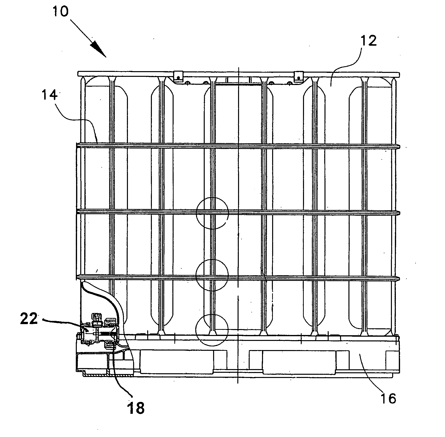
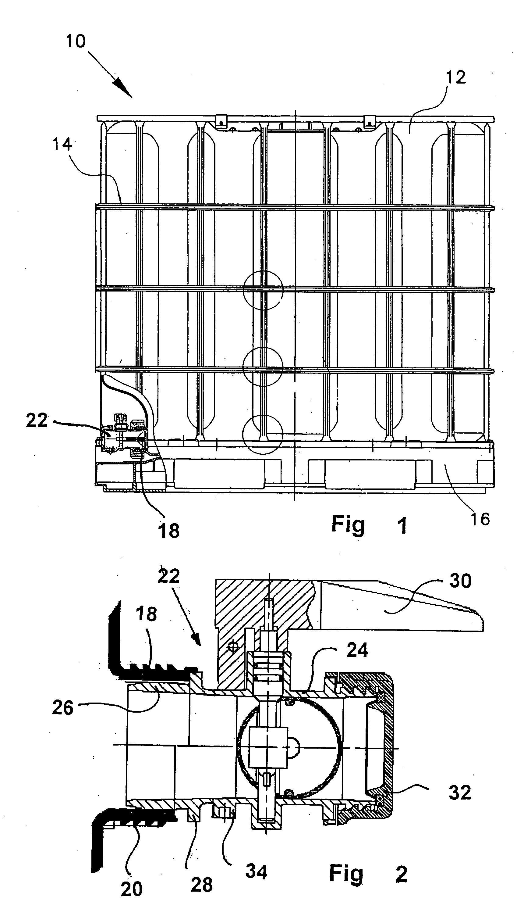
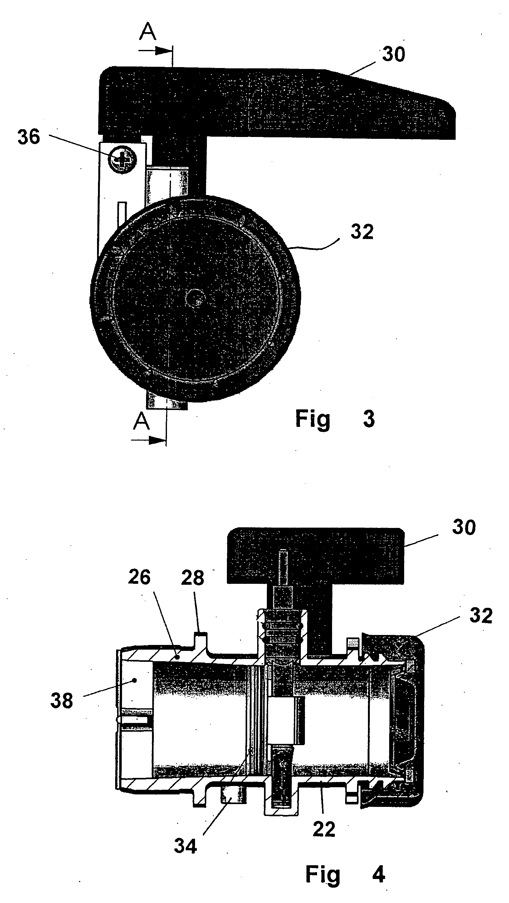
[0050] Turning now to the drawing, and in particular to FIG. 1, there is shown a side elevation of a pallet container according to the present invention, generally designated by reference numeral 10. The pallet container 10 has a thin-walled inner container 12 of thermoplastic material, a tubular lattice frame 14 closely surrounding the inner plastic container 12 as support ...


PUM

PropertyMeasurementUnit
Lengthaaaaaaaaaa
Lengthaaaaaaaaaa
Lengthaaaaaaaaaa

Abstract

A pallet container for the storage and transport of liquid or free-flowing goods, includes a thin-walled inner container of thermoplastic material, a tubular lattice frame closely surrounding the inner plastic container in the form of a support jacket, and a bottom pallet upon which the inner plastic container rests and with which the tubular lattice frame is securely fixed. The inner plastic container includes for withdrawal of liquid goods at the lower side, approximately in mid-section in a side wall near its bottom a blown, calibrated tubular pipe for allowing attachment of a closeable discharge fitting which is fixedly welded with its tubular housing to the calibrated tubular pipe of the inner container.

Description

CROSS-REFERENCES TO RELATED APPLICATIONS [0001] This application is a continuation of prior filed copending PCT International application no. PCT / EP2005 / 002039, filed Feb. 25, 2005, which designated the United States and on which priority is claimed under 35 U.S.C. §120, and which claims the priority of German Patent Application, Serial No. 20 2004 003 236.8, filed Feb. 27, 2004, pursuant to 35 U.S.C. 119(a)-(d), the subject matter of which are incorporated herein by reference.BACKGROUND OF THE INVENTION [0002] The present invention relates, in general, to a pallet container for the storage and transport of liquid or free-flowing goods. The present invention further relates to a method of making such a pallet container. [0003] The structural configuration of such pallet containers is generally known and its essential components are described e.g. in German publication no. DE-A 34 42 701. Typically, discharge fittings are screwed by means of a coupling nut onto an outer thread of the...

Claims


Application Information

Patent Timeline
IPC IPC(8): B65D6/40B29C65/02B29C65/06B29C65/08B29C65/20B29C65/48B29C65/78B65D77/04B65D77/06
CPCB29C65/02Y10T29/49826B29C65/0672B29C65/08B29C65/20B29C65/48B29C65/7802B29C2793/0018B29C2793/009B29K2105/26B29L2031/7126B65D77/0466B65D2213/02B29C66/53247Y10T29/49B29C65/06B29C66/8322B29C66/612B29C66/24221B29C66/1284B29C66/131B29C66/12821B65D77/06B65D19/00
Inventor SCHMIDT, KLAUS PETERWEYRAUCH, DETLEVPRZYTULLA, DIETMARWURZER, ERNST
Owner MAUSER WERKE GMBH
Learn More