Method of and apparatus for determining the amount of impurity in gas

a technology of impurity and gas, which is applied in the direction of color/spectral property measurement, optical radiation measurement, instruments, etc., can solve the problems of difficult measurement of the concentration of impurity gas, difficult measurement of trace impurity gas, etc., to prevent the possibility of measuring error, easy to replace, and easy to evacuate

Inactive Publication Date: 2006-01-19
OTSUKA DENSHI CO LTD
View PDF3 Cites 36 Cited by
  • Summary
  • Abstract
  • Description
  • Claims
  • Application Information

AI Technical Summary

Benefits of technology

[0013] This apparatus for determining the concentration of impurity mixed in gas, is in accordance with an invention identical with the invention for the method of determining the concentration of impurity mixed in gas. With this apparatus, there can accurately be measured the concentration of the impurity alone with the influence of the sample gas removed.
[0014] Preferably, the light source and the detector are separately housed in respective airtight containers. According to the arrangement above-mentioned, the airtight containers can readily be evacuated and filled with gas which does not absorb light at the wavelength of the absorption spectrum of the impurity. This prevents the light source and the detector from being contaminated. Accordingly, the impurity spectrum to be measured is not affected by contamination, thus preventing a measuring error from occurring.
[0015] It is preferable that the joint portion between the first airtight container and the cell is capable of maintaining the airtightness in the first airtight container with the cell removed, and that the joint portion between the second airtight container and the cell is capable of maintaining the airtightness in the second airtight container with the cell removed. According to the arrangement above-mentioned, the cell can readily be replaced with other cell with the airtightness of each of the airtight containers maintained.
[0016] Preferably, a power source unit for supplying an electric power to the light source or the detector, is disposed outside of the first and second airtight containers. Such an arrangement prevents the effect of radiation from the power source unit serving as a heat generating source, from being lowered.
[0017] It is preferable that there is also disposed a computer for achieving the function of each of the first light intensity measuring means, the second light intensity measuring means, the storing means, the third light intensity measuring means and the concentration measuring means, and that the computer is disposed outside of the first and second airtight containers. Such an arrangement too prevents the effect of radiation from the computer from being lowered, likewise in the power source unit.

Problems solved by technology

In a conventional method of determining the amount of impurity in gas with the use of an infrared spectrometer, when measuring the concentration of a trace impurity gas, the infrared absorption peak of the main component gas overlaps the infrared absorption peak of the trace gas component, causing the measurement of the trace impurity gas to be very difficult.
This makes the measurement of the concentration of the impurity gas makes difficult.

Method used


Image

  • Method of and apparatus for determining the amount of impurity in gas
  • Method of and apparatus for determining the amount of impurity in gas
  • Method of and apparatus for determining the amount of impurity in gas

Examples


Embodiment Construction

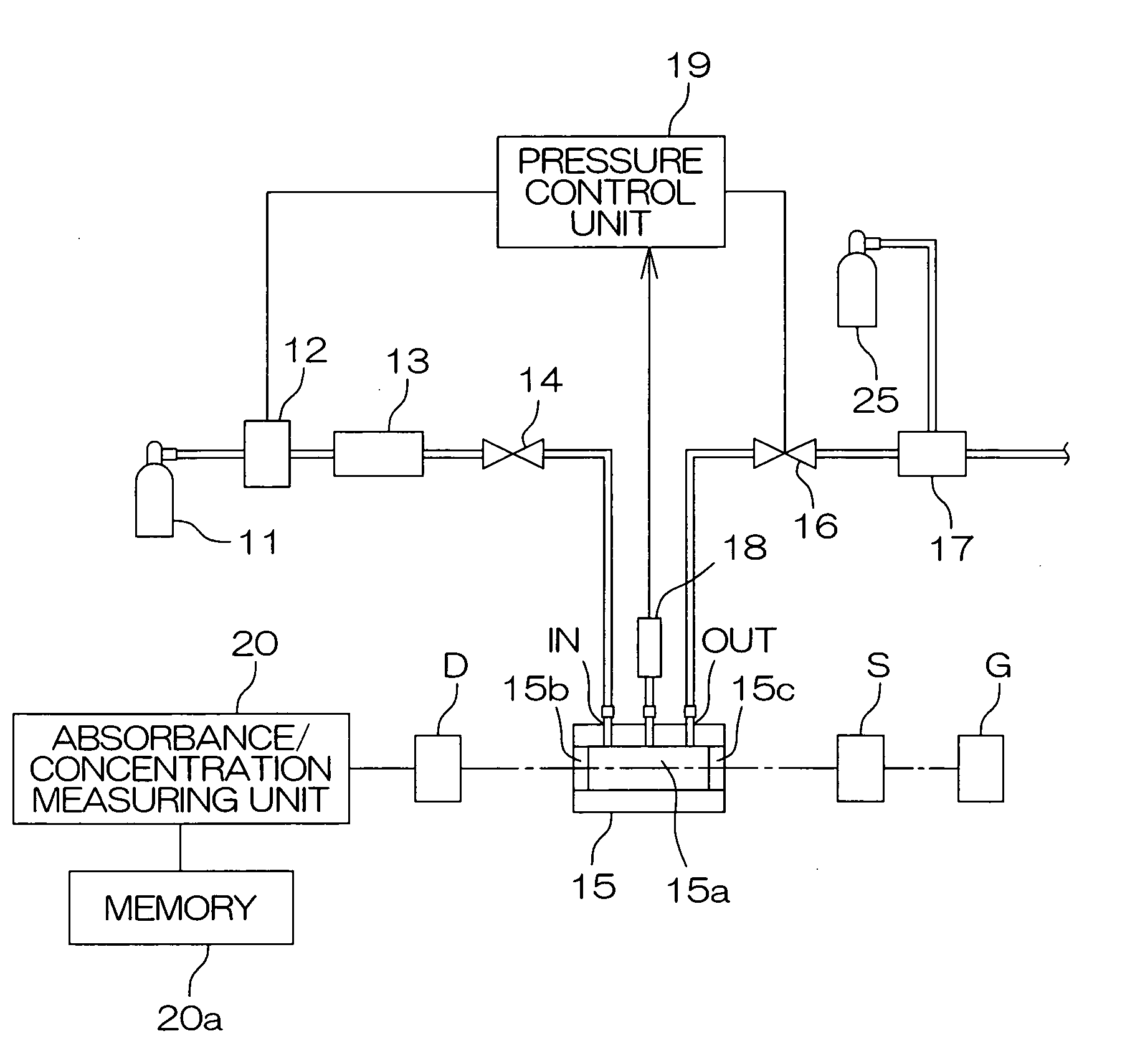
[0026]FIG. 1 is a view illustrating a measuring system for measuring the light intensity of a sample gas (reference) with impurity removed therefrom.

[0027] In FIG. 1, a sample bomb 11 containing a sample gas is connected to a gas inlet IN of a gas cell 15 through a mass flow controller 12 for adjusting the flow amount of gas, an impurity refining device 13 for removing impurity and an openable valve 14. This passage is referred to as a first gas introducing system.

[0028] On the other hand, an adjusting valve 16 and a vacuum generator 17 (which may also be a pressure ejector) for generating a negative pressure, are connected to a gas outlet OUT of the gas cell 15. The vacuum generator 17 is connected to a high-pressure gas bomb 25 containing air or nitrogen. With this construction, a pressure control of 0.1 Pa is possible in respect of atmosphere pressure (100 KPa).

[0029] In the present embodiment, the gas cell 15 serves as the first, the second and the third cell of the same opti...


PUM

PropertyMeasurementUnit
pressureaaaaaaaaaa
surface temperatureaaaaaaaaaa
wavelengthaaaaaaaaaa

Abstract

Impurity is removed from gas, the resultant gas is introduced into a cell 15, and the intensity of light transmitted through the cell 15 is measured as a reference. Gas containing impurity of which concentration is known, is introduced into the cell 15, and the intensity of light transmitted through the cell 15 is measured with the temperature and pressure maintained at those used at the measurement of the reference light intensity. Then, the absorbance of the impurity is obtained according to the ratio of the two light intensity data obtained by the two measurements above-mentioned. The impurity absorbance thus obtained is stored, in a memory 20a, as a function of an impurity concentration. Gas containing impurity of which concentration is unknown, is introduced into the cell 15, and the intensity of light transmitted through the cell 15 is measured with the temperature and pressure maintained at those used at the measurements above-mentioned. The absorbance of the impurity is obtained according to the last-measured light intensity and the reference light intensity. The absorbance thus obtained is applied to the function, thereby to obtain the impurity concentration.

Description

BACKGROUND OF THE INVENTION [0001] 1. Field of the Invention [0002] The present invention relates to method of and apparatus for determining the amount of impurity mixed in gas. [0003] 2. Description of Related Art [0004] In a conventional method of determining the amount of impurity in gas with the use of an infrared spectrometer, when measuring the concentration of a trace impurity gas, the infrared absorption peak of the main component gas overlaps the infrared absorption peak of the trace gas component, causing the measurement of the trace impurity gas to be very difficult. [0005] The following description will discuss, by way of example, a measurement of a trace moisture contained, as impurity gas, in ammonia gas. [0006] There has conventionally been proposed a method of measuring such a trace moisture at a wavenumber at which the infrared absorption of ammonia and the infrared absorption of the moisture do not overlap each other (Japanese Patent Laid-Open Publication No. 2001-...

Claims


Application Information

Patent Timeline
Patent Type & Authority Applications(United States)
IPC IPC(8): G01N21/17G01N21/03G01N21/3554
CPCG01N21/3504G01N21/35G01N33/00G01N21/45G01N2021/5957
Inventor OKA, KOICHINITTA, SATOSHI
Owner OTSUKA DENSHI CO LTD
Why Eureka
Try Eureka