Transformer or inductor containing a magnetic core having abbreviated sidewalls and an asymmetric center core portion

a technology of transformers and inductor components, applied in transformers/inductance details, coils, electrical devices, etc., can solve the problems of reducing and reducing the size of the resultant device, so as to improve the electrical performance of the device and reduce the resultant device footprint

Active Publication Date: 2006-01-19
LITTELFUSE INC
View PDF9 Cites 26 Cited by
  • Summary
  • Abstract
  • Description
  • Claims
  • Application Information

AI Technical Summary

Benefits of technology

[0006] A general object of the present invention is to provide an electrical device in the form of a transformer or an inductor with a two-part magnetic core wherein the sidewalls of the skirt extend down an abb

Problems solved by technology

However, this can give disadvantages in terms of leakage inductance, DC resistance, and total harmonic distortion.
For example, U.S. Pat. No. 4,760,366 (Mitsui) illustrates a ferrite core having a central core portion including circular ends and a flattened rectangular central region, rendering the resultant core structure and electrical device relatively wide and thereby unduly consumptive of valuable PCB space.
Another limitation of these prior art electrical devices is that the central core regions are symmetrical about a plane parallel to the PCB mounting

Method used


Image

  • Transformer or inductor containing a magnetic core having abbreviated sidewalls and an asymmetric center core portion
  • Transformer or inductor containing a magnetic core having abbreviated sidewalls and an asymmetric center core portion
  • Transformer or inductor containing a magnetic core having abbreviated sidewalls and an asymmetric center core portion

Examples


Embodiment Construction

[0029] Electrical devices in accordance with the present invention form an inductor if there is at least one coil present, and a transformer if there are at least two mutually-coupled coils present. In this specification, the word “device” includes both inductors and transformers.

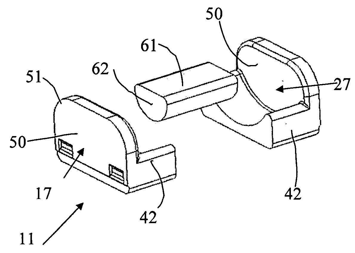
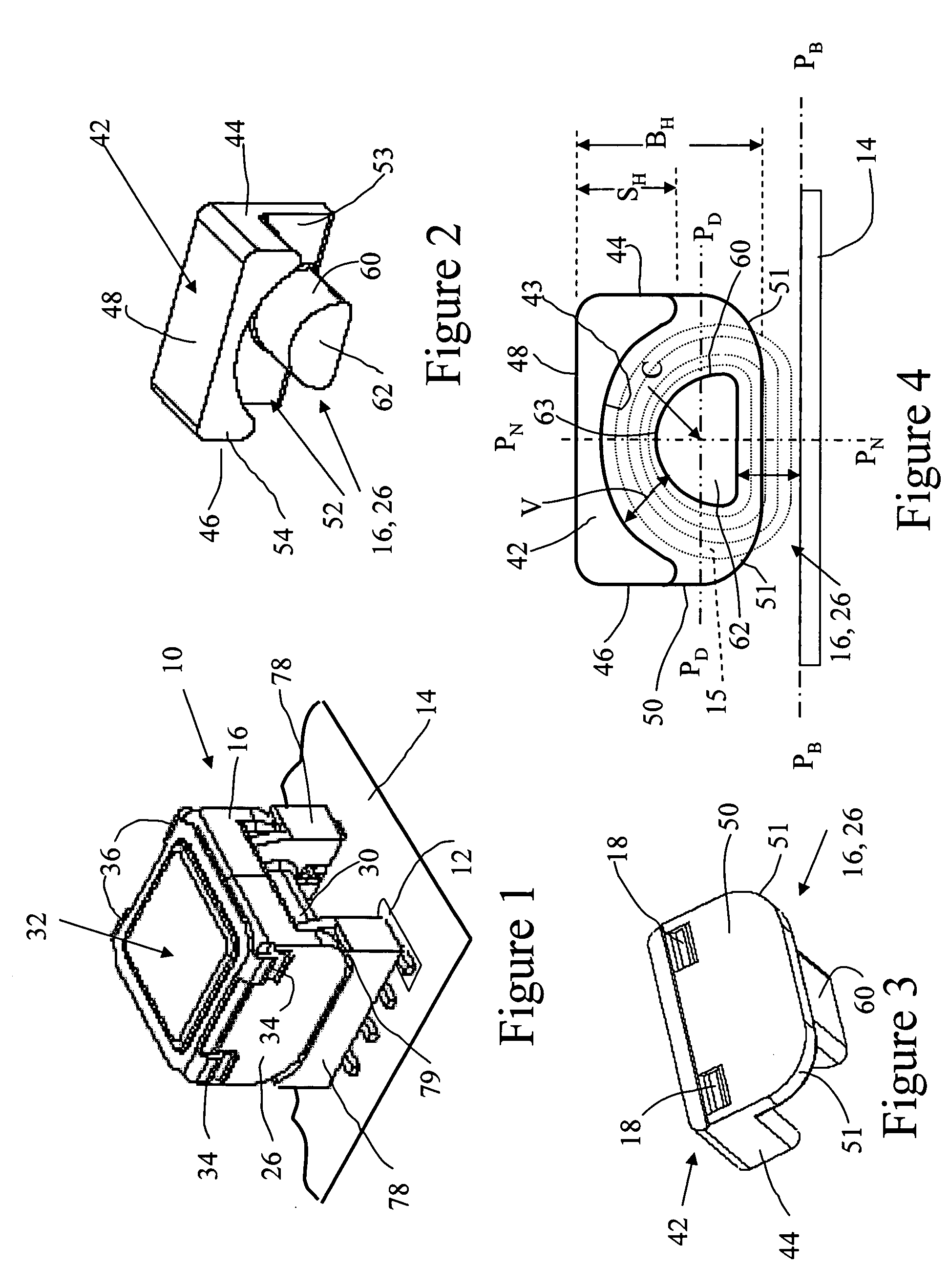
[0030]FIG. 1 shows an assembly view of a device 10 incorporating principles of the present invention. The device 10 has at least two mutually-coupled coils and therefore functions as a transformer. As shown in FIG. 1, the device 10 is surface-mounted, i.e., by a solder reflow process, directly to aligned traces 12 of a PCB 14 thereby to connect coil terminal ends with associated circuitry (not shown) of an electrical circuit including the PCB 14, and thereby mechanically to secure the device 10 to the PCB 14. Alternatively, the device 10 may be provided with dependent pins enabling the device to be through-hole mounted to the PCB.

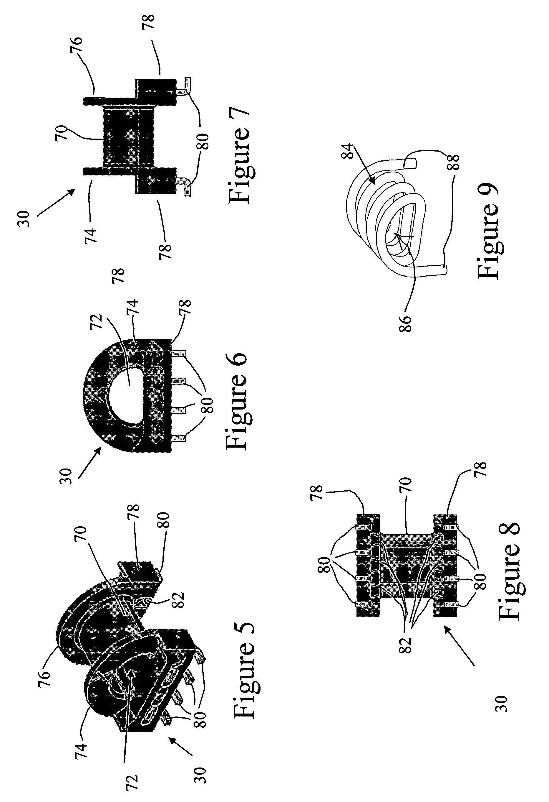
[0031] The device 10 includes a first core half 16 and a second core half 26...


PUM


Abstract

An inductor or transformer for mounting on a PCB has a two-part magnetic core structure and at least one coil wound on a bobbin. Each core part has a backwall and an abbreviated outer skirt extending from the backwall and an asymmetric center core element extending from the backwall in the same direction as the outer skirt along a longitudinal axis parallel with the mounting plane and including the centroid of the center core element. The center core element is asymmetric relative to a dividing plane parallel with the mounting plane and including the longitudinal axis, such that a greater portion of the center core element lies on a side of the dividing plane than on an opposite side of the dividing plane. In one preferred form, the center core element has a cross-sectional shape resembling a “D” character turned on its side, or “lazy D” shape.

Description

BACKGROUND OF THE INVENTION FIELD OF THE INVENTION [0001] This invention relates to an electric device in the form of a transformer or an inductor, having a two-part magnetic core; and this invention relates to cross-sectional geometry and resultant shape of a magnetic core part of such a device. INTRODUCTION TO THE INVENTION [0002] Electrical devices for use as transformers and inductors commonly comprise a magnetic core inserted into a bobbin around which one or more wire coils are wound. When used for power supply, data, or telecommunications applications, such devices are mounted on printed circuit boards (PCBs), along with other electronic elements. Due to the large number of elements present on the board, it is important that the amount of space occupied by the electrical device be minimized. However, it is also important that the electrical device maintain a certain level of performance required for maximum data or power throughput. The conventional approach for reducing the ...

Claims


Application Information

Patent Timeline
IPC IPC(8): H01F27/24
CPCH01F27/027H01F2005/043H01F27/255
Inventor REPPE, JOHNHUUMALA, DEAN E.HOLDAHL, JIMMY D.SETTERGREN, TODD
Owner LITTELFUSE INC
Why Eureka
Try Eureka