Valve and fueling strategy for operating a controlled auto-ignition four-stroke internal combustion engine

Active Publication Date: 2006-01-26
GM GLOBAL TECH OPERATIONS LLC
View PDF56 Cites 65 Cited by
  • Summary
  • Abstract
  • Description
  • Claims
  • Application Information

AI Technical Summary

Benefits of technology

[0011] The present invention provides these and other desirable aspects in a method of operating a four-stroke internal combustion engine with extended capability at low engine loads while maintaining or improving combustion quality, combustion stability and engine out emissions.
[0012] In accordance with one aspect the present invention, during part load engine operation negative exhaust and intake valve overlap is controlled to trap and compress combusted gases within the combustion chamber prior to the intake event intake valve opening to effect higher chamber pressures at lower engine loads. In accordance with another aspect of the invention, a split-injection strategy is employed at intermediate part load engine operation whereby a first fraction of fuel is injected late during the exhaust cycle into the trapped and compressed combusted gases within the

Problems solved by technology

That is to say providing an optimal air/fuel ratio of substantially 14.6 to 1 that results in substantially complete consumption of the fuel and oxygen delivered to the engine.
Better air/fuel ratio control is achieved with a MPFI arrangement; however, conditions such as wall wetting and intake runner dynamics limit the precision with which such control is achieved.
However, lean-burn systems s

Method used


Image

  • Valve and fueling strategy for operating a controlled auto-ignition four-stroke internal combustion engine
  • Valve and fueling strategy for operating a controlled auto-ignition four-stroke internal combustion engine
  • Valve and fueling strategy for operating a controlled auto-ignition four-stroke internal combustion engine

Examples


Embodiment Construction

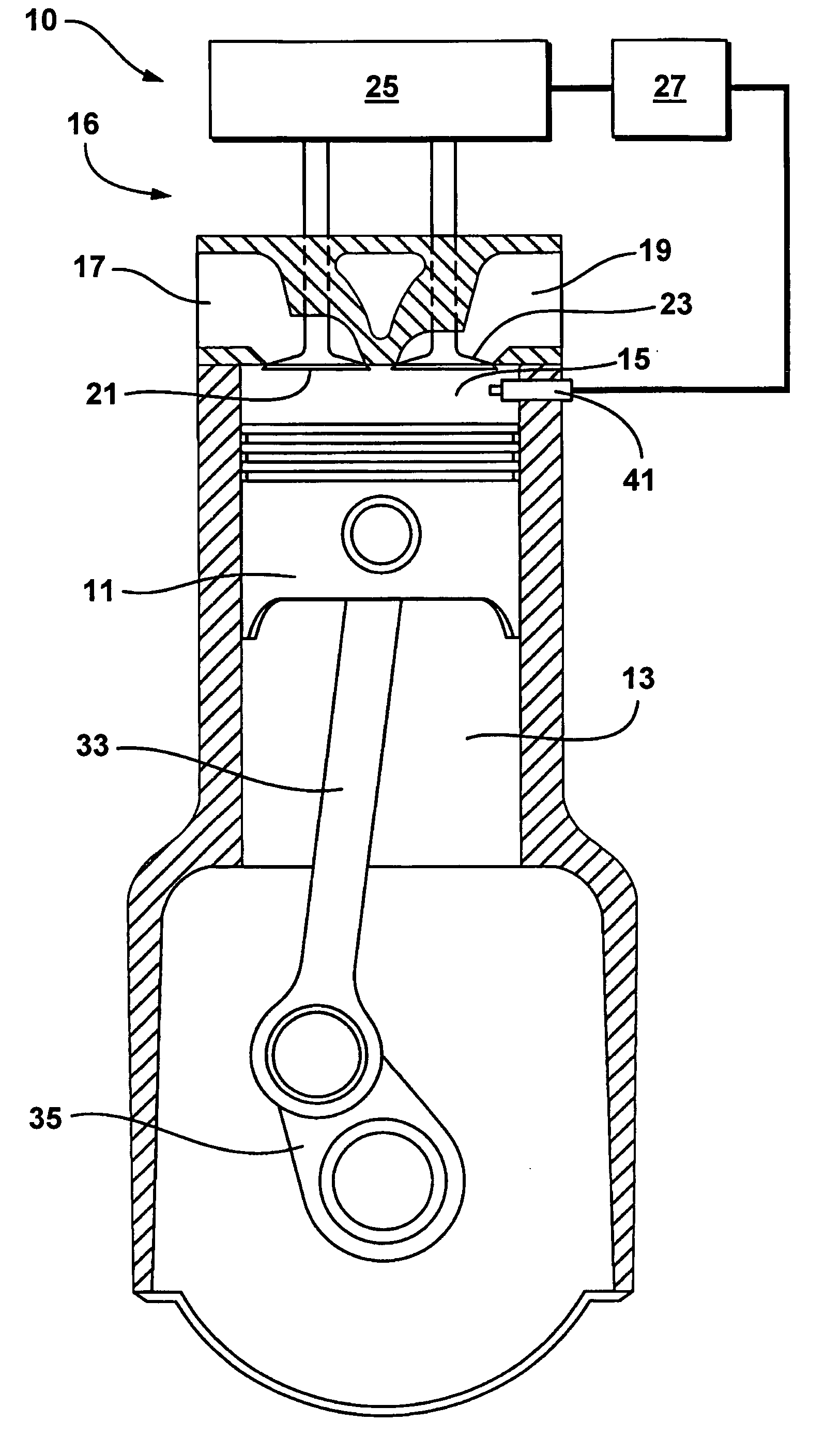
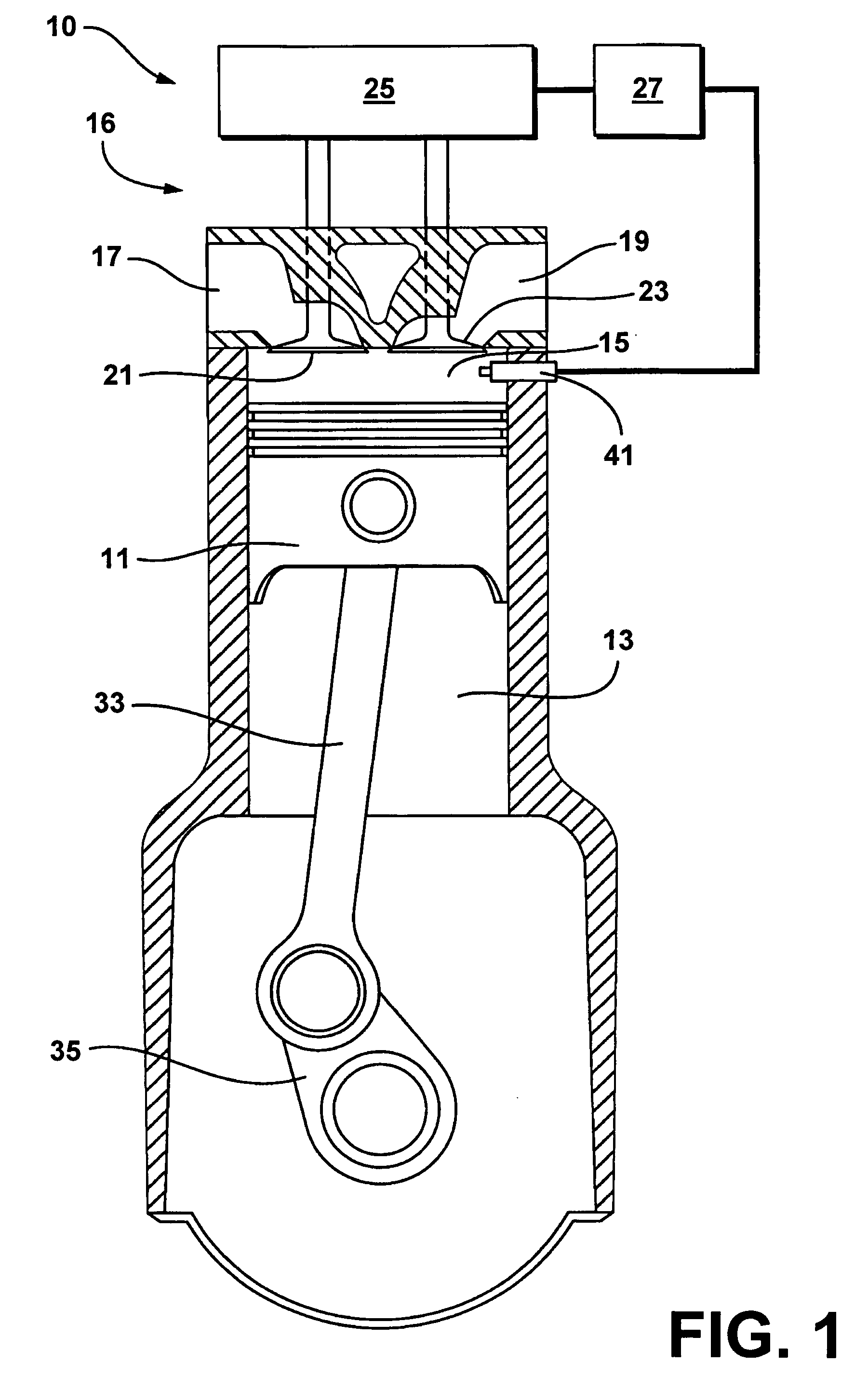
[0025] With reference first to FIG. 1, an exemplary single cylinder four-stroke internal combustion engine system (engine) 10 suited for implementation of the present invention is schematically illustrated. It is to be appreciated that the present invention is equally applicable to a multi-cylinder four-stroke internal combustion engine. The present exemplary engine 10 is shown configured for direct combustion chamber injection (direct injection) of fuel vis-a-vis fuel injector 41. Alternative fueling strategies including port fuel injection or throttle body fuel injection may also be used in conjunction with certain aspects of the present invention; however, the preferred approach is direct injection. Similarly, while widely available grades of gasoline and light ethanol blends thereof are preferred fuels, alternative liquid and gaseous fuels such as higher ethanol blends (e.g. E80, E85), neat ethanol (E99), neat methanol (M100), natural gas, hydrogen, biogas, various reformates, s...


PUM


Abstract

Part load operating point for a controlled auto-ignition four-stroke internal combustion engine is reduced without compromising combustion stability through negative valve overlap control operative to retain and compress combusted gases within the combustion chamber into which fuel is introduced. Combustion chamber pressures and temperatures are increased as engine load decreases. Various split-injection fuel controls are implemented during low and intermediate part load operation whereas a single-injection fuel control is implemented during high part load operation. Split-injections are characterized by lean fuel/air ratios and single-injections are characterized by either lean or stoichiometric fuel/air ratios. Controlled autoignition is thereby enabled through an extended range of engine loads while maintaining acceptable combustion stability and emissions.

Description

TECHNICAL FIELD [0001] The present invention is related to operating a four-stroke internal combustion engine. BACKGROUND OF THE INVENTION [0002] The automotive industry is continually researching new ways of improving the combustion process of the internal combustion engine in an effort to improve fuel economy, meet or exceed emission regulatory targets, and to meet or exceed consumer expectations regarding emissions, fuel economy and product differentiation. [0003] Most modern conventional internal combustion engines attempt to operate around stoichiometric conditions. That is to say providing an optimal air / fuel ratio of substantially 14.6 to 1 that results in substantially complete consumption of the fuel and oxygen delivered to the engine. Such operation allows for exhaust gas aftertreatment by 3-way catalysts which clean up any unconsumed fuel (HC) and combustion byproducts such as NOx and CO. Most modern engines are fuel injected having either throttle body injection (TBI) or...

Claims


Application Information

Patent Timeline
IPC IPC(8): F02B3/00
CPCF02B1/12F02B2075/027F02B2075/125F02D13/0215F02D13/0219Y02T10/18F02D41/3047F02D41/402F02M25/0752Y02T10/44Y02T10/123F02D13/0265F02M26/01Y02T10/12Y02T10/40
Inventor KUO, TANG-WEIBROWN, BARRY L.NAJT, PAUL M.SLOANE, THOMPSON MILTONBARTHS, HARDO
Owner GM GLOBAL TECH OPERATIONS LLC
Why Eureka
Try Eureka