
Ion source with particular grid assembly

Inactive Publication Date: 2006-01-26
ASIA OPTICAL INT LTD
View PDF6 Cites 60 Cited by
  • Summary
  • Abstract
  • Description
  • Claims
  • Application Information

AI Technical Summary

Benefits of technology

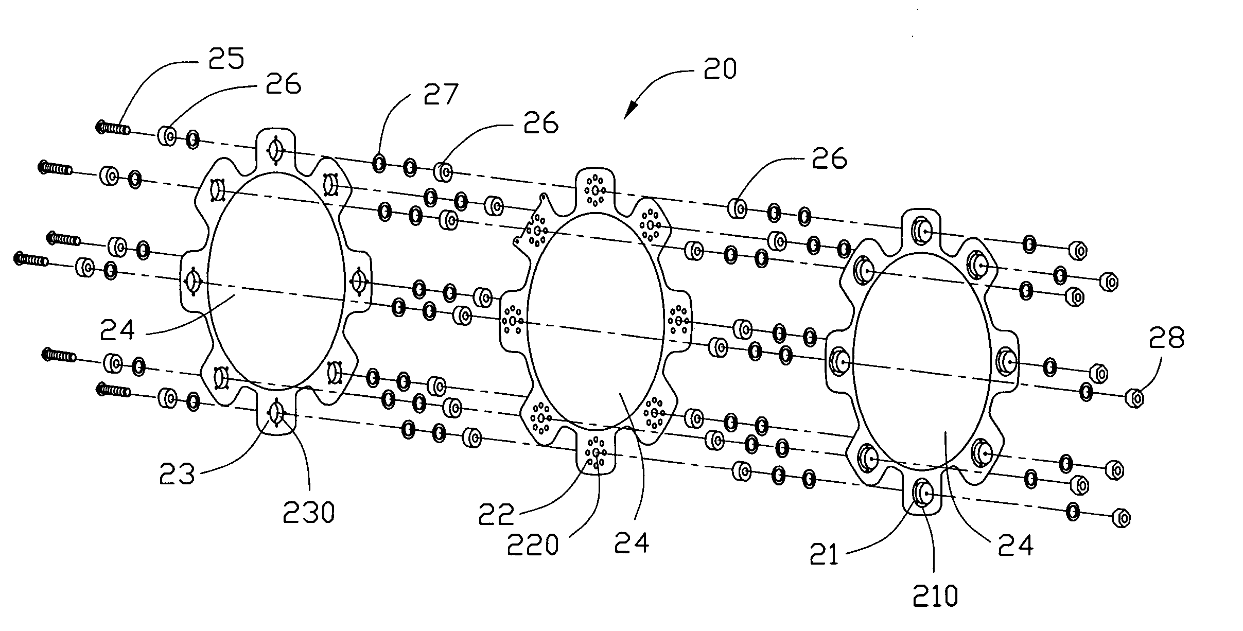
[0013] Another object of the present invention is to provide an ion source with a particular grid assembly. This particular grid assembly focuses the extracted ions into a converged ion beam for energy concentration, thereby increasing the thin film deposition throughput and yield, and thus decreasing the production cost.
[0016] Since the grid assembly of the ion source of the present invention is disposed at the open end of the discharge chamber in an inwardly curved profile, a converged ion beam is obtained, and thus the quality of the resultant thin film is improved due to deposition density increase, thereby increasing throughput and yield of the thin film.

Problems solved by technology

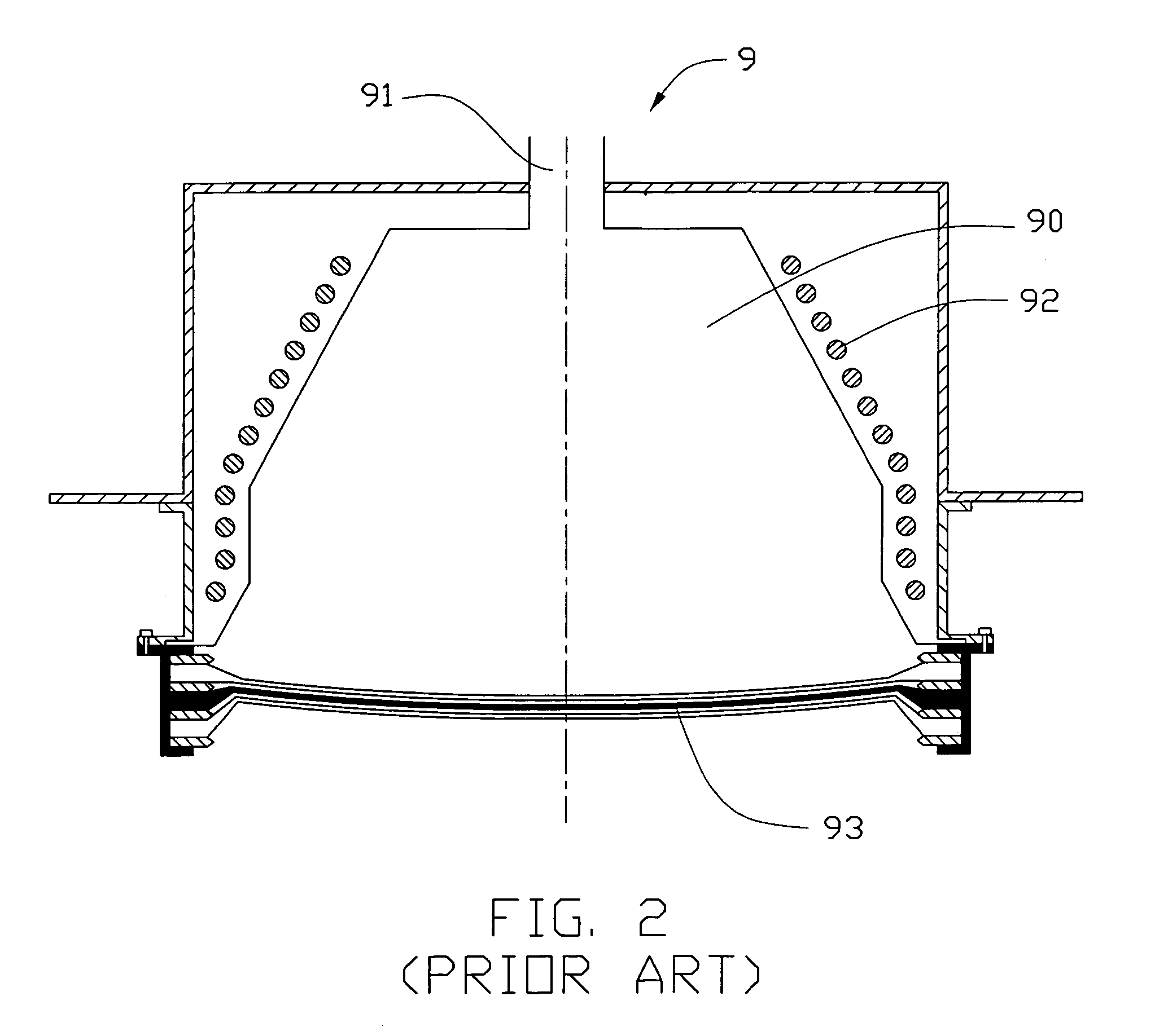
However, the ion beam tends to diverge or becomes larger due to the mutual repulsion of ions bearing the same charge.
Although the surface area of the substrate 70 is entirely covered by the ion beam 74, this large cross-sectional area of the ion beam 74 disadvantageously causes energy loss and thus loss of adhesion of the resultant layer over the substrate 70 due to deposition density reduction.
This results in reduced yield and throughput, which is unwanted.

Method used


Image

  • Ion source with particular grid assembly
  • Ion source with particular grid assembly
  • Ion source with particular grid assembly

Examples


Embodiment Construction

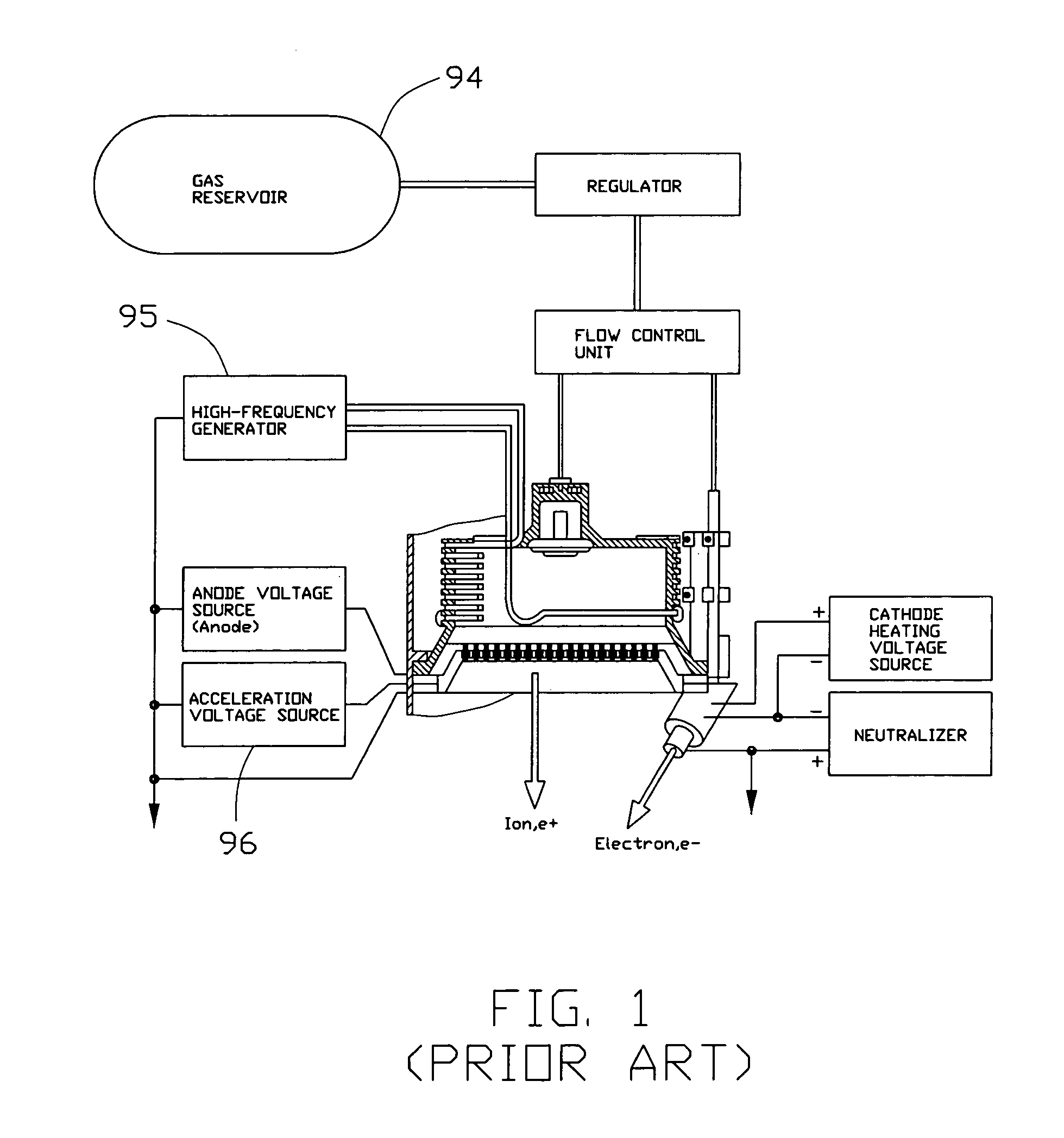
[0024] Referring to FIGS. 5 and 6, an ion source 1 in accordance with the present invention has a configuration similar to that of the prior art. The ion source 1 is positioned in a deposition chamber or vacuum chamber 100 and is intended for optical thin film deposition by IAD process. The ion source 1 includes a discharge chamber or plasma chamber 10, an ionizable gas source for supplying ionizable gas into the discharge chamber 10, an actuator 11 positioned around the discharge chamber 10, an ion beam extraction device arranged at an open end of the discharge chamber 10, and an outer shell 30 surrounding the discharge chamber 10 and the actuator 11. The discharge chamber 10 is made of an electrically non-conductive material. The outer shell 30 may be made of metal. The actuator 11 may be in the form of an RF coil connected to a high frequency generator (shown in FIG. 1) for generating a high-frequency electromagnetic alternating field, which ionizes the gas present in the dischar...


PUM


Abstract

An ion source (1) to be used in optical thin film deposition by IAD process includes a discharge chamber (10), a gas source, an actuator (11), a grid assembly (20) and an outer shell (30). The grid assembly includes a screen grid (21), an accelerator grid (22) and a decelerator grid (23). The screen grid is kept at anode potential and is disposed near the ions. The accelerator grid is kept at cathode potential and is spaced from the screen grid. The decelerator grid is equal to the ground and is disposed beyond the accelerator grid. Each grid has a curved central portion (24) defining a plurality of apertures aligned with those of the other two grids to form extraction channels for an ion beam (40). When disposing the grid assembly at one end of the discharge chamber, the curved central portions of the three grids are arranged in an inwardly curved manner toward the interior of the discharge chamber, and thus the ion beam is extracted from the grid assembly in a converged manner to have a sequentially reduced cross-sectional area.

Description

BACKGROUND OF THE INVENTION [0001] 1. Field of the Invention [0002] The present invention relates to an ion source, and particularly relates to an ion source with a particular grid assembly, which is intended to be used in optical thin film deposition. [0003] 2. Description of Prior Art [0004] Currently, optical thin film coating technology has been widely applied in high technology fields, such as laser optics and fiber communications fields. A thin film coating can be either a single-layer or a multi-layer coating on a substrate where several thin films are deposited on top of one another to achieve the required reflection / transmission via interference effects. The substrate may be a glass, metal, ceramic, or plastic substrate. An optical glass substrate is the most commonly used substrate. Each layer of the thin film coating is very thin, typically in the range between several nanometers and several microns. The number of layers may be one or a few hundreds. One of the applicatio...

Claims


Application Information

Patent Timeline
IPC IPC(8): G21G5/00
CPCH01J2237/31732H01J37/08
Inventor SHANG, CHANG CHEN E.
Owner ASIA OPTICAL INT LTD
Learn More