
Resonator system

a technology of resonance system and resonator, which is applied in the field of resonance system, can solve the problems of limiting the possible geometric design, preventing or complicating the short pulse width, and limiting the possibility of geometric design, so as to achieve the effect of reducing the loss, reducing the cost, and high quality factor

Active Publication Date: 2006-01-26
BRUKER SWITZERLAND AG
View PDF14 Cites 8 Cited by
  • Summary
  • Abstract
  • Description
  • Claims
  • Application Information

AI Technical Summary

Benefits of technology

The invention is a resonator system that uses individual resonators to create a high-quality RF field for a variety of applications. The resonators are designed to have a high quality factor and can be made of superconducting material. The resonators can be arranged in different ways to optimize the RF field and can be nested or stacked to create a larger system using small substrates. The system can also have different resonance frequencies for different applications. The method allows for the adjustment of the individual resonators to achieve maximum field homogeneity. Overall, the invention provides a resonator system with improved RF field quality and flexibility for various applications.

Problems solved by technology

This strongly limits the possible geometric designs.
A substantial problem involved with the use of superconducting receiving resonators is the static magnetization generated by the superconductor which can produce field inhomogeneities and strongly inhibit obtaining narrow lines in high-resolution NMR.
Moreover, the limited critical current in the superconductor limits the maximum coil current of the transmitting pulse and thereby complicates or prevents short pulse widths for a given NMR flip angle.
For small sample diameters, the somewhat complicated structure limits the geometry.
Moreover, the construction of hybrid birdcage resonators is quite demanding.
The meandering structure of the resonator additionally generates undesired electric fields which have a negative influence on the losses in conducting samples.
Moreover, this arrangement has a very poor field homogeneity in the z direction, which reduces the S / N ratio, and a very low current carrying capacity, which precludes short pulse angles.
However, this is technically not possible. FIG. 15b shows an equivalent diagram of such a resonator system.
The efficiency is however small, since the current carrying elements are located remote from the sample.
Moreover, the conventional arrangements require a large amount of space.
For this reason, resonators for further frequencies are located considerably further away from the sample or cannot be mounted at all due to lack of space.
Another disadvantage is that these devices are quadrature-suitable to only a limited degree, namely only if the conductors 109 are disposed at an angle of less than 90°.
Disadvantageously, this arrangement can only be used for small samples and generates a large stray field which produces strong coupling with other resonators.
A result of this rotation of the useful RF field relative to the remote RF field is that the mounting and, in particular, inductive coupling of further resonators for additional frequencies in such a manner that the coupling between the resonator system and the further resonators can be neglected, is extremely difficult.
This embodiment requires even more space than an arrangement with Helmholtz pairs such that the resonators for further frequencies are located at a considerably greater distance from the sample or cannot be mounted at all due to lack of space.

Method used


Image

  • Resonator system
  • Resonator system
  • Resonator system

Examples


Embodiment Construction

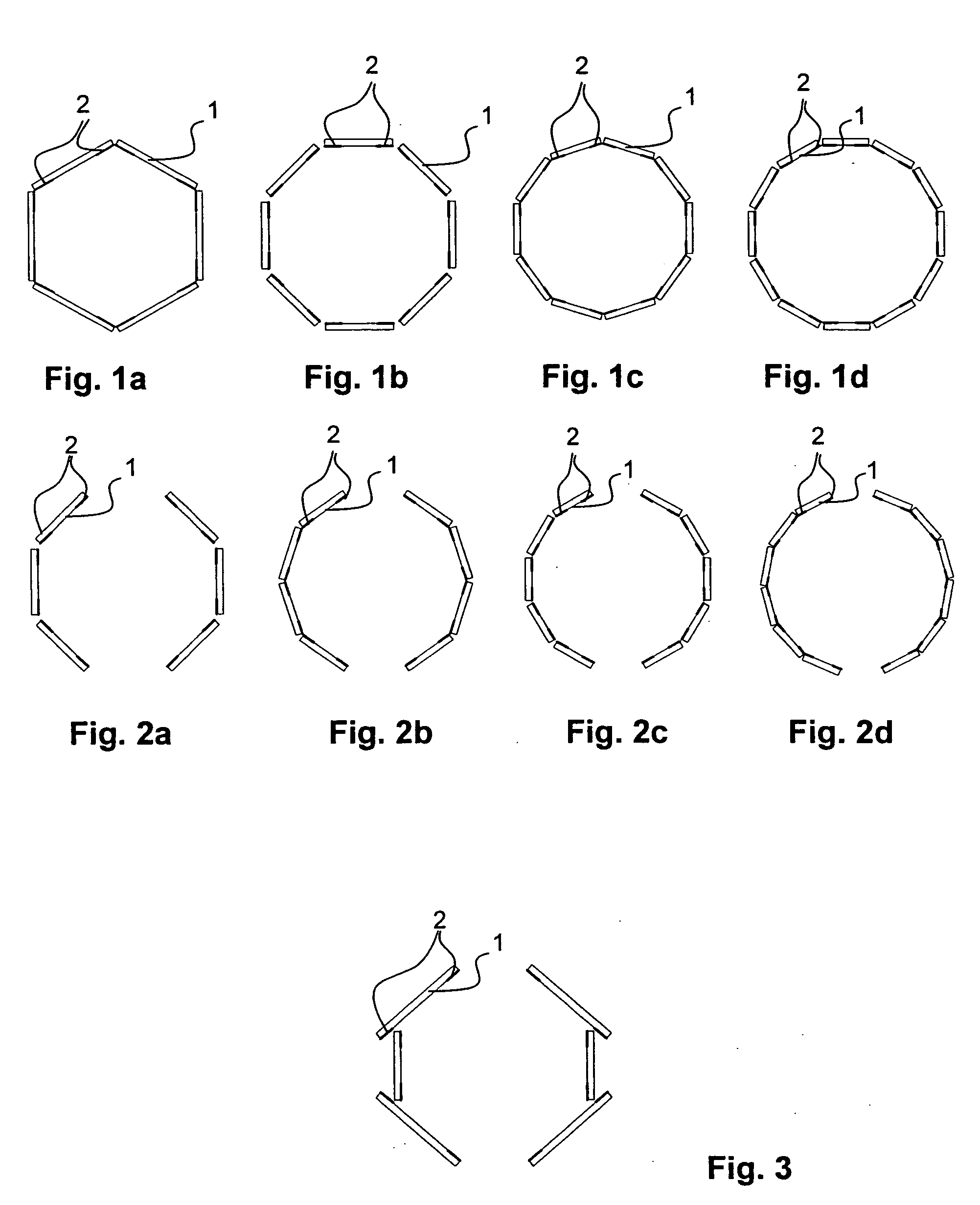
[0069]FIGS. 1a-d and FIGS. 2a-d show sections of different embodiments of an inventive resonator system parallel to the xy plane. N=4(i+1) individual resonators 2 disposed onto planar substrates 1 (FIGS. 1b, d and FIGS. 2b, d) are preferably symmetrically disposed about a sample. A number of N=2(i−2) individual resonators 2 is also reasonable for linearly polarized coils.

[0070]FIGS. 1a-d show resonator systems, wherein the individual resonators 2 are disposed on the surfaces of a polyhedron. The illustrated embodiments have an N-fold rotational and planar symmetry and are more suited for circularly polarized coils (quadrature emission and detection), whereas the embodiments shown in FIG. 2 merely show a 2-fold rotational and planar symmetry and are therefore only suited for linearly polarized coils.

[0071] As shown in the example of FIG. 3, the size of the individual resonators 2 must not be identical. It is however useful to respect at least one, optimally both symmetry planes of ...


PUM


Abstract

A resonator system for generating a radio frequency (RF) magnetic field in a volume under investigation of a magnetic resonance (MR) arrangement, comprises a number N of individual resonators (2) which surround the volume under investigation and which are each disposed on a flat dielectric substrate (1) around a z-axis, wherein the individual resonators (2) have windows (8) through each of which one individual RF field is generated in the volume under investigation in single operation of the individual resonators (2) and, through cooperation among the individual resonators (2), a useful RF field (7) is generated in the volume under investigation, wherein a remote RF field (6) is asymptotically generated far outside of the resonator system, and the spatial distribution of the useful RF field (7) is substantially mirror-symmetrical relative to a first plane A which contains the z-axis, and that of the asymptotic remote RF field (6) is substantially mirror-symmetrical relative to a second plane B which contains the z-axis, the useful RF field (7) extending substantially parallel to the first plane A in the volume under investigation, wherein the number of individual resonators (2) is N>4 and wherein, during operation of the resonator system at at least one point in time, the substrate plane of at least one individual resonator (2) subtends an angle of more than 40° with respect to the direction of the useful RF field (7) in the volume under investigation, and at least one further individual resonator (2) subtends an angle of less than 40° with respect to the direction of the useful RF field (7) in the volume under investigation, is characterized in that the first plane A is not rotated about the z-axis relative to the second plane B or is rotated by less than 360° / (N+1). The inventive resonator system realizes a resonator system with improved field homogeneity and full quadrature suitability, high quality factor and large efficiency using straightforward constructional measures.

Description

[0001] This application claims Paris Convention priority of DE 10 2004 035 851.6 filed Jul. 23, 2004 the complete disclosure of which is hereby incorporated by reference. BACKGROUND OF THE INVENTION [0002] The invention concerns a resonator system for generating a radio frequency (RF) magnetic field in the investigational volume of a magnetic resonance (MR) arrangement, comprising a number N of individual resonators which surround the volume under investigation and which are each disposed on flat, dielectric substrates about a z-axis, wherein the individual resonators have windows through each of which one individual RF field is generated in the volume under investigation during single operation of the individual resonators, and, through cooperation among the individual resonators, a useful RF field is generated in the volume under investigation, wherein a remote RF field is asymptotically generated far outside of the resonator system, the spatial distribution of the useful RF field...

Claims


Application Information

Patent Timeline
Patent Type & Authority Applications(United States)
IPC IPC(8): G01V3/00
CPCG01R33/34007G01R33/34023G01R33/34092G01R33/34061G01R33/34076G01R33/34046
Inventor FREYTAG, NICOLAS
Owner BRUKER SWITZERLAND AG
Learn More