
System and method for providing tempered fluid

a technology of tempering system and fluid, which is applied in the direction of process and machine control, physical therapy, instruments, etc., can solve the problems of reducing the duration of use of emergency equipment, affecting the quality of fluid provided, so as to reduce the flow of cold fluid, increase the temperature of mixed fluid, and increase the flow

Active Publication Date: 2006-02-02
MAGARL
View PDF22 Cites 26 Cited by
  • Summary
  • Abstract
  • Description
  • Claims
  • Application Information

AI Technical Summary

Benefits of technology

[0003] Thermally controlled or thermostatic mixing valves are well known. Valves of this type receive both hot and cold fluid, typically water, and allow the fluids to mix to an intermediate temperature. The temperature is controlled using a thermally responsive control member, such as a thermostat, to assist in maintaining the fluid temperature according to an established setting.
[0012] In such a stagnant fluid circulation system, when a fixture (such as an eyewash station) is eventually actuated, the thermostat is often exposed to mixed water at a temperature below the set point temperature, even if the ratio of water from the hot and cold fluid supplies otherwise would be proportioned (if the hot fluid were at temperature) to produce mixed fluid at the desired temperature. Accordingly, responsive changes in the thermostat cause the valve control assembly to move to a position that increases the flow of hot fluid relative to the flow of cold fluid, thus increasing the mixed fluid temperature. As the valve continues to receive the supply of fluid from the hot fluid supply line that was formerly stagnant, the thermostat continues to cause the valve control assembly to move to a position that further increases flow from the hot fluid supply line and / or decreases the flow of cold fluid. If a sufficient volume of stagnant fluid is in the supply line between the hot fluid supply and the mixing valve, this process may continue until the thermostat has caused the valve assembly to move to a position wide-open to maximize the flow of fluid from the hot fluid source.
[0013] Eventually, hot fluid from in the hot fluid supply (such as a water heater) progresses to the mixing valve. Because the valve control assembly is now wide-open to the hot fluid inlet, a large volume of hot fluid enters the valve housing through the hot fluid supply line that had previously been the source of the stagnant (and cooler) fluid. Once the hot fluid reaches the thermostat after mixing with whatever cold fluid is entering the valve, the thermostat responds to the temperature increase, causing the valve control assembly to move to reduce the flow of hot fluid and / or increase the flow of cold fluid. The length of time for the thermostat to respond as such and move the valve control assembly by a sufficient amount to reduce the temperature of mixed fluid below the set point can be long enough to permit a quantity of water above the set point temperature to flow from the valve.
[0025] Illustratively according to this aspect of the invention, the apparatus further comprises a means for dampening temperature change of the first fluid prior to entry into the first fluid inlet of the thermostatic mixing valve so that the mixing valve can adjust to a particular temperature increase over a given time period.
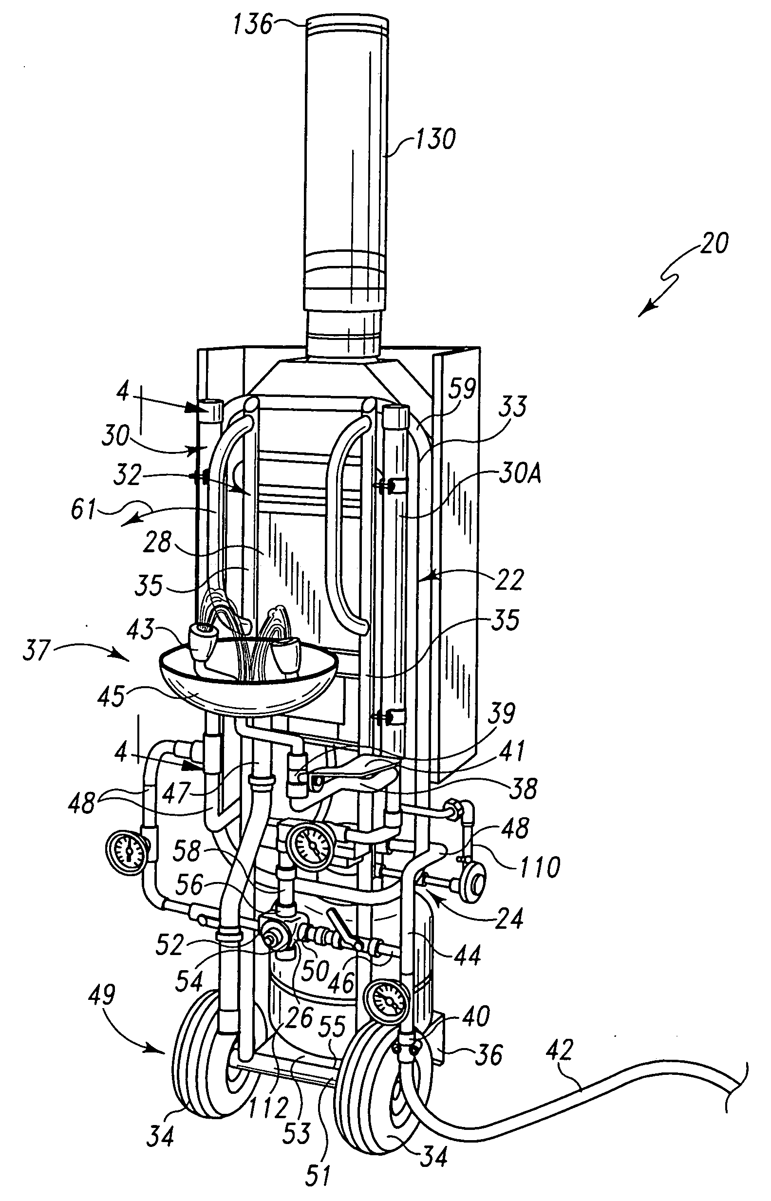
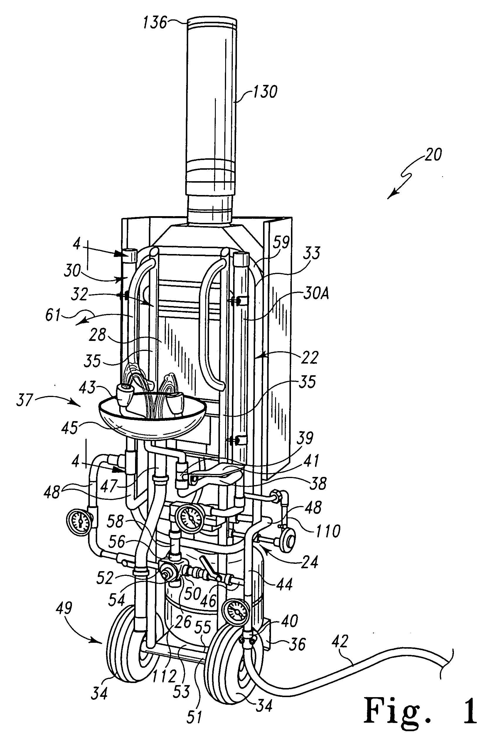
[0049] According to another aspect of the invention a decontamination apparatus comprising a fluid heater, a cold fluid supply line, a hot fluid supply line for supplying hot fluid from the fluid heater to a thermostatic mixing valve, the thermostatic mixing valve having a hot fluid inlet for receiving fluid from to the hot fluid supply line, a cold fluid inlet for receiving fluid from the cold fluid supply line, and a mixed fluid outlet for supplying fluid to a mixed fluid supply line through which one, the other, or both of the hot and cold fluids flow from the thermostatic mixing valve, an emergency fixture connected to the mixed fluid supply line for supplying fluid therefrom to a user and configured to deliver the mixed fluid at a flow rate and pattern to decontaminate effectively at least a portion of the user's body, and a diffuser coupled between the hot fluid supply line and the thermostatic mixing valve for increasing the time over which a temperature change is observed at the hot fluid inlet.
[0053] Additionally illustratively according to this aspect of the invention, the apparatus further comprises a diffuser positioned in the circulation network to receive fluid from the heater, the diffuser configured to increase the time over which a temperature increase is observed at the inlet of the fluid from the heater to the mixing valve.

Problems solved by technology

In each of these industries, workers may be exposed to chemicals that may cause serious tissue damage and destruction.
In emergency fixture systems such as eyewash and emergency shower systems, even ground water of a moderate temperature (such as in the range of 50 degrees to 60 degrees F., as is common) is often perceived to be too cold, possibly discouraging sufficient duration of use of the emergency equipment.
In addition, in northern climates, the ground water itself is sometimes barely above freezing, commonly near 35 degrees F. Under these circumstances, an emergency shower and eyewash system relying solely upon ground water often provides water that would be too cold to be endured for a sufficient period of time, even by a victim of a chemical accident.
Such remote worksites typically do not have a ready supply of hot water.
Thus, workers at such sites exposed to chemicals or other irritants typically do not have access to emergency fixture systems that provide an adequate supply of tempered fluid, properly directed, for a sufficient period of time.
For example, if the cold water supply fails and only hot water in the range of 140 degrees F. to 160 degrees F. is supplied, the user could suffer burns that may be more serious than the exposure being treated.

Method used


Image

  • System and method for providing tempered fluid
  • System and method for providing tempered fluid
  • System and method for providing tempered fluid

Examples


example 1

[0122]

TABLE 1TemperatureTemperatureTemperaturePressure of hot(° F.) of(° F.) of(° F.) ofwater at mixingTimeCold WaterHot WaterMixed Waterpoint3:00:42 PM43.4509171.784.63361.923:00:52 PM43.3573171.92484.81983.023:01:02 PM43.3417172.6785.61646.553:01:12 PM43.4275173.252144.0856.403:01:22 PM43.4119173.739165.6077.143:01:32 PM43.4275174.084169.9026.423:01:42 PM43.4509174.396171.4837.073:01:52 PM43.5757174.592171.9856.913:02:02 PM44.0981174.896172.6836.653:02:12 PM45.1031175.031172.926.813:02:22 PM46.2003175.024173.347.123:02:32 PM47.0322175.207173.4897.123:02:42 PM47.7779175.274173.6387.113:02:52 PM48.3911175.301173.8076.983:03:02 PM45.5001175.288173.6993.033:03:12 PM44.2462175.031121.812.323:03:22 PM44.1292174.59295.17761.993:03:32 PM43.9032174.49791.03162.853:03:42 PM43.9655174.16689.28463.013:03:52 PM44.1994173.93688.49881.583:04:02 PM43.7784173.82187.97952.063:04:13 PM43.5133173.63187.86072.733:04:23 PM43.3495173.57787.60831.673:04:33 PM43.2715173.3683.15731.273:04:43 PM43.1544173.2...


PUM


Abstract

The present invention is directed to methods and apparatus for tempering the temperature of a liquid in a fluid conducting system. More particularly, the invention relates to tempering the temperature of water supplied to a fixture from a water heater in a fluid conducting system.

Description

[0001] This application claims priority to U.S. Provisional Application No. 60 / 592,710, filed Jul. 30, 2004, herein incorporated by reference in its entirety.BACKGROUND AND SUMMARY OF THE INVENTION [0002] The present invention concerns a method and apparatus for tempering the temperature of a liquid in a fluid conducting system. More particularly, the invention relates to tempering the temperature of water supplied to a fixture from a water heater in a fluid conducting system. [0003] Thermally controlled or thermostatic mixing valves are well known. Valves of this type receive both hot and cold fluid, typically water, and allow the fluids to mix to an intermediate temperature. The temperature is controlled using a thermally responsive control member, such as a thermostat, to assist in maintaining the fluid temperature according to an established setting. [0004] One particular application of thermostatic mixing valves is in connection with emergency shower and eyewash systems. Toxic ...

Claims


Application Information

Patent Timeline
IPC IPC(8): A61H33/00A61H33/04
CPCA61H35/02G05D23/132A61H33/60A61H33/0095
Inventor ROBERT, EVELEIGHGARY, COOK
Owner MAGARL
Learn More