
Eureka
For R&D, Eureka makes reading and utilizing patents & technical documents easy.
Eureka AIR
Designed for self-driven R&D workflows. Generate viable solutions, solve complex R&D challenges, empower your innovation with AI.

Eureka Materials
Designed for material experts only. Revolutionize your material R&D, from search, analyze, to developing new materials.

TechResearch
Generate reliable direction feasibility study reports for your R&D in just a few steps.

TechSeek
Discover and master advanced knowledge NOW. Basics, ideas, possibilities, all at once.

TechMind
As an expert in R&D Theories, TechMind can generates customized viable solutions instantly.

TechRisk
Analyze your overall solution with one click, know your potential R&D risks in advance.

TechMonitor
Get weekly tech updates, stay abreast of the latest tech innovations and key insights.
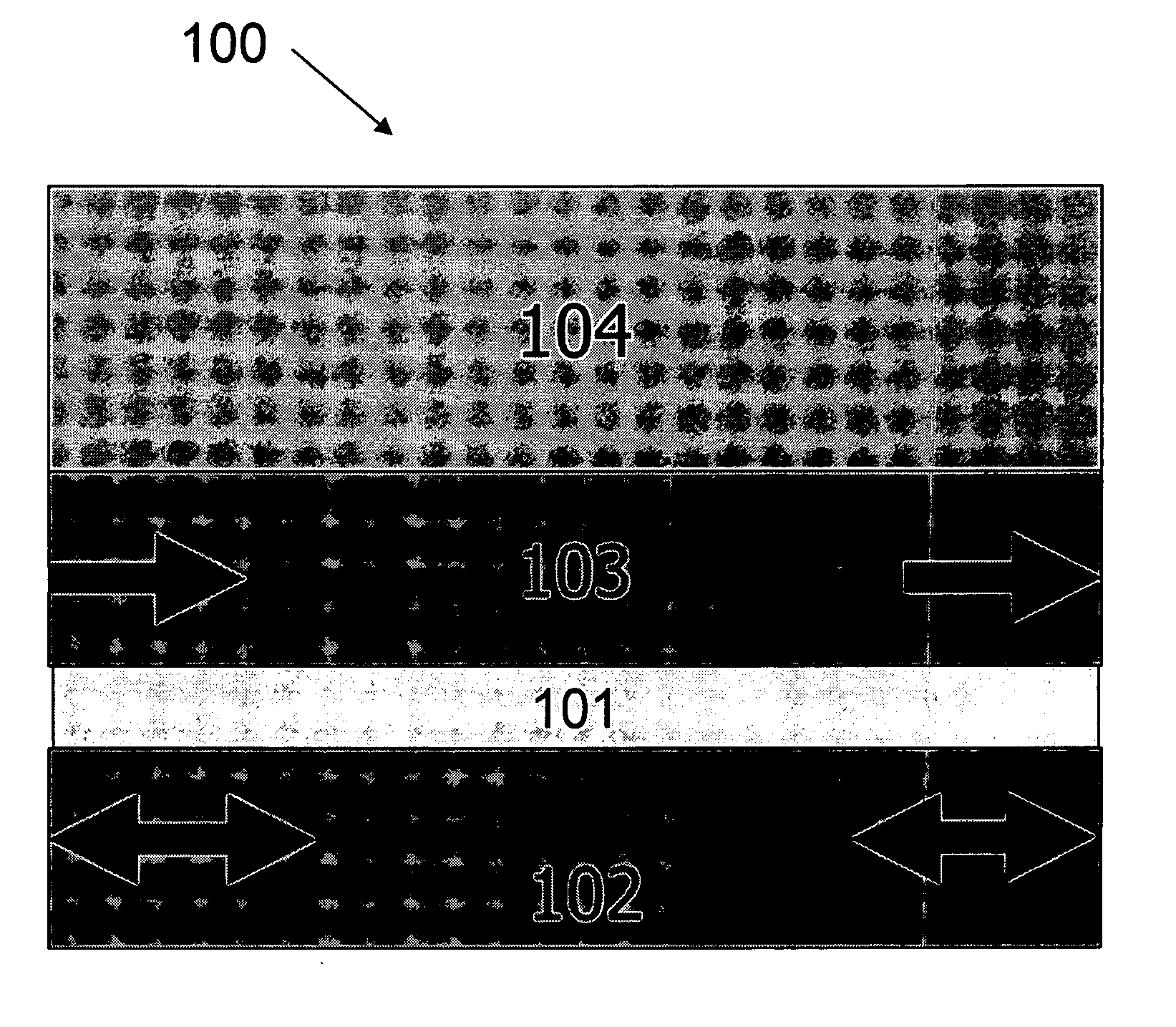
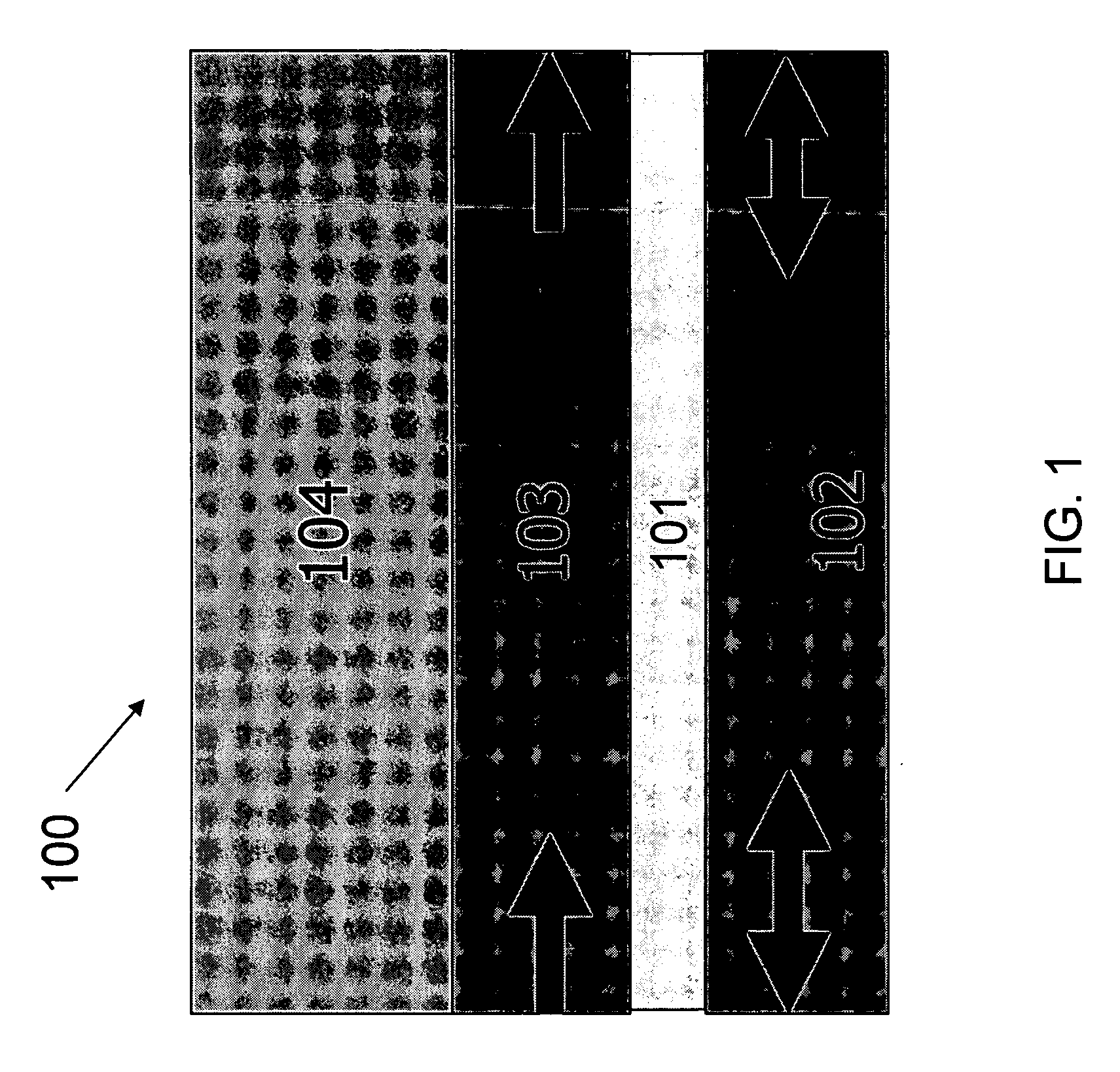
Methods for the fabrication of thermally stable magnetic tunnel junctions
- Summary
- Abstract
- Description
- Claims
- Application Information
AI Technical Summary
Benefits of technology
Problems solved by technology
Method used
Image

Examples
example 1
Production of a CoFe / Aluminum Oxide / CoFe Magnetic Tunnel Junction Using a CO / CO2 Oxidizing Gas
[0045] This example illustrates a method for producing an MTJ composed of an aluminum oxide tunnel barrier layer sandwiched between two Co0.9Fe0.1 ferromagnetic layers. In this example, an Al layer and a CoFe layer were exposed separately to an oxidizing gas composed of a mixture of CO and CO2 having a pCO:pCO2 ratio of 0.1 in order to test for the oxidation. One advantage of this method is that the oxidation process was removed from the sputter deposition process. This allowed the total pressure of the CO / CO2 oxidizing gas to become an independent parameter and eliminated the need to mix CO / CO2 with Ar gas, as in a sputter plasma approach, and removed concerns about changes to the calculated reactivity due to a sputter plasma.
[0046] A CoFe ferromagnetic layer was deposited onto a Ti buffer layer having a thickness of approximately 100 nm using DC magnetron sputtering from a CoFe target i...
example 2
Production of a CoFe / Aluminum Oxide / CoFe Magnetic Tunnel Junction Using an H2O / H2 Oxidizing Gas
[0059] This example illustrates a method for producing an MTJ composed of an aluminum oxide tunnel barrier layer sandwiched between two CoFe ferromagnetic layers. A pure Al layer was deposited onto a Ti buffer layer, as described in Example 1, using DC magnetron sputter deposition from an Al target. The resulting Al layer was subsequently oxidized in an H2O / H2 oxidizing gas.
[0060] In these experiments, a first sample composed of a 0.5 nm thick Al layer deposited on a Ti buffer layer was exposed to an oxidizing gas containing H2O and H2 at a pH2O:pH2 ratio of about 2×10⁴. The Al layer was exposed to the oxidizing gas at a pressure of 500 Torr for 20 minutes at 200° C., then capped with 3 nm of Ti. A second sample composed of a 0.5 nm thick Al layer deposited on a Ti buffer layer was exposed to an oxidizing gas of O2. The Al layer was exposed to this oxidizing gas at a pressure of 0.02 Tor...
example 3
Production of a CoFe / Yttrium Oxide / CoFe Magnetic Tunnel Junction Using an H2O / H2 Oxidizing Gas
[0062] This example illustrates a method for producing an MTJ composed of a yttrium oxide tunnel barrier layer sandwiched between two CoFe ferromagnetic layers. A pure Y layer was deposited onto a Ti buffer layer using DC magnetron sputter deposition from a Y target. The resulting Y layer was subsequently oxidized in an H2O / H2 oxidizing gas.
[0063] In these experiments, a first sample composed of a 1 nm thick Y layer deposited on a Ti buffer layer was exposed to an oxidizing gas containing H2O and H2 at a pH2O:pH2 ratio of about 2×10⁻⁴. The Y layer was exposed to the oxidizing gas at a pressure of 1 Torr for 20 minutes at room temperature, then capped with 3 nm of Ti.
[0064] An XPS analysis of the sample was conducted as described above and the data indicated that the Y layer had been completely oxidized. An XPS analysis of a CoFe layer treated in an oxidizing gas of H2O and H2 under the s...
PUM
| Property | Measurement | Unit |
|---|---|---|
| Temperature | aaaaa | aaaaa |
| Temperature | aaaaa | aaaaa |
| Thickness | aaaaa | aaaaa |
Abstract
Description
Claims
Application Information
 - R&D Engineer
- R&D Manager
- IP Professional
- Industry Leading Data Capabilities
- Powerful AI technology
- Patent DNA Extraction
Browse by: Latest US Patents, China's latest patents, Technical Efficacy Thesaurus, Application Domain, Technology Topic, Popular Technical Reports.
© 2024 PatSnap. All rights reserved.Legal|Privacy policy|Modern Slavery Act Transparency Statement|Sitemap|About US| Contact US: help@patsnap.com