Integrated cooler for electronic devices

a technology for electronic devices and coolers, applied in the field of cooling systems, can solve the problems of requiring improved systems for heat removal, large power supplies and auxiliary components, and premature device failure, and achieve the effects of improving cooler performance, small required space, and high thermal efficiency

Inactive Publication Date: 2006-02-02
INDAL DESIGN LAB
View PDF26 Cites 70 Cited by
  • Summary
  • Abstract
  • Description
  • Claims
  • Application Information

AI Technical Summary

Benefits of technology

[0013] Accordingly, it is an object of the present invention to provide an integrated cooler for electronic devices, which is capable of significantly improving of cooler performances such as small required space, high thermal efficiency, low sound level and increased blower efficiency.

Problems solved by technology

Cooling is important because if left unchecked, heat can cause electronic devices to malfunction during use or lead to premature device failure.
Additionally, improved processors require larger power supplies and auxiliary components that generate increased amounts of heat and require improved systems for heat removal.
The trend toward smaller and thinner electronic devices having larger, faster processors renders the traditional heat removal cooling systems inadequate for several reasons.
First, smaller devices having faster processors result in an increased density of heat producing electronic components leading to higher localized concentrations of heat.
Also, a decreased amount of space is available for localized temperature regulating devices such as traditional heat sinks.
Lastly, a decreased amount of space is available to create ventilation paths that pass by heat sources.
By this reason, the thermal efficiency of this heat dissipation device is insufficient.
However, arrangement of electric drive inside blower casing according U.S. Pat. No. 6,700,781 requires additional space increasing a thickness of the cooling device and cause a vibration of the flat stator and magnetized rotor due to a rise of oscillation forces in a direction perpendicular to the planes of the flat stator and the magnetized rotor.
In one's turn the vibration generates an increasing sound level thus contradicts with modern requirements for cooling devices.
On the other hand mentioned vibration cause an energy losses thus decrease the motor efficiency of the electric drive and, correspondingly, a blower efficiency.
However, according to this design main and additional heat exchanging means located outside of the radial impeller thus significantly increase a space required for such devices.

Method used


Image

  • Integrated cooler for electronic devices
  • Integrated cooler for electronic devices
  • Integrated cooler for electronic devices

Examples


Embodiment Construction

[0033] Preferred embodiment of the present invention will be described in detail below with reference to the accompanying drawings. The numbering of components is consistent throughout, with the same components having the same number.

[0034]FIGS. 1-12 show an embodiment of the present invention.

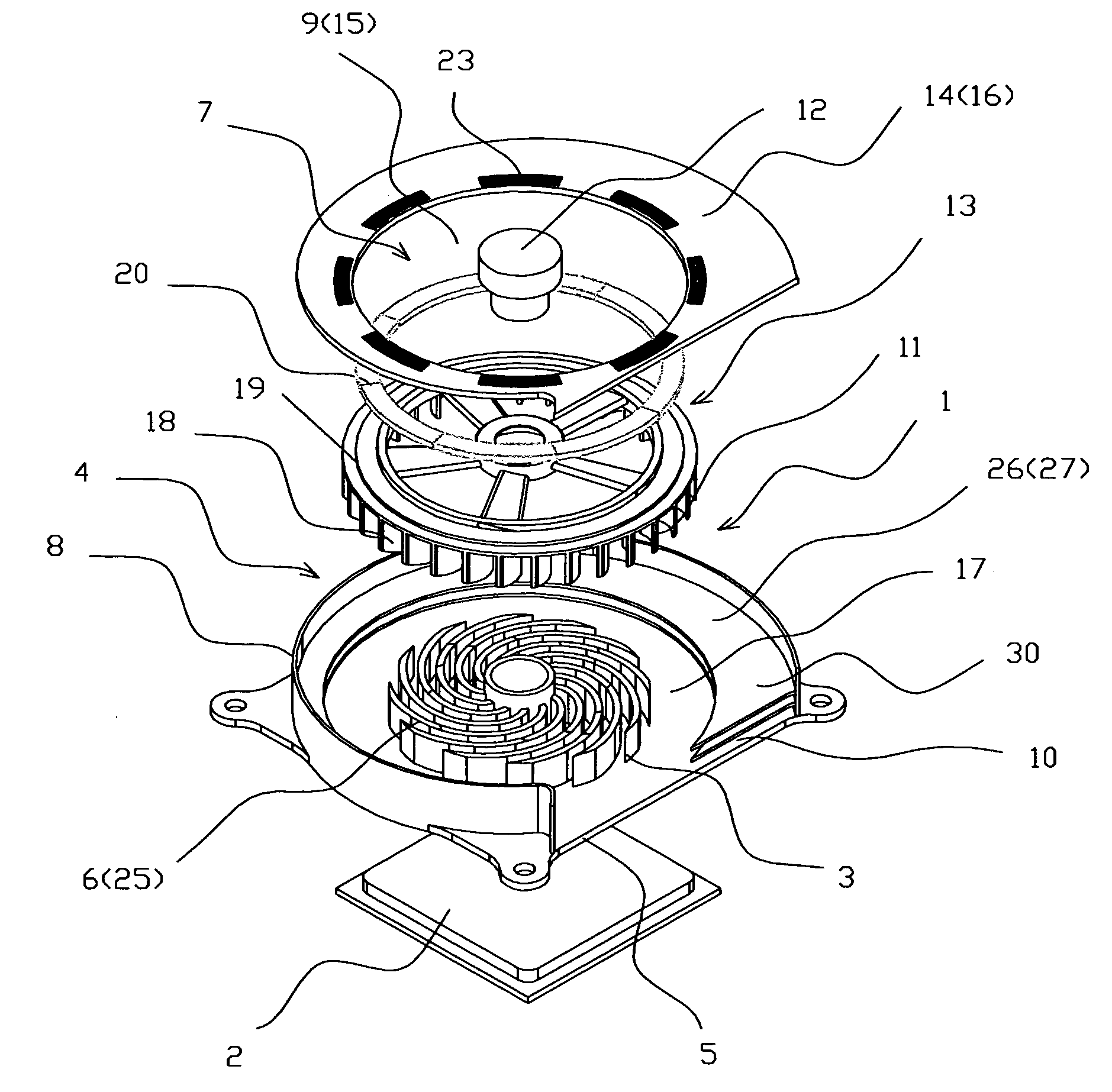
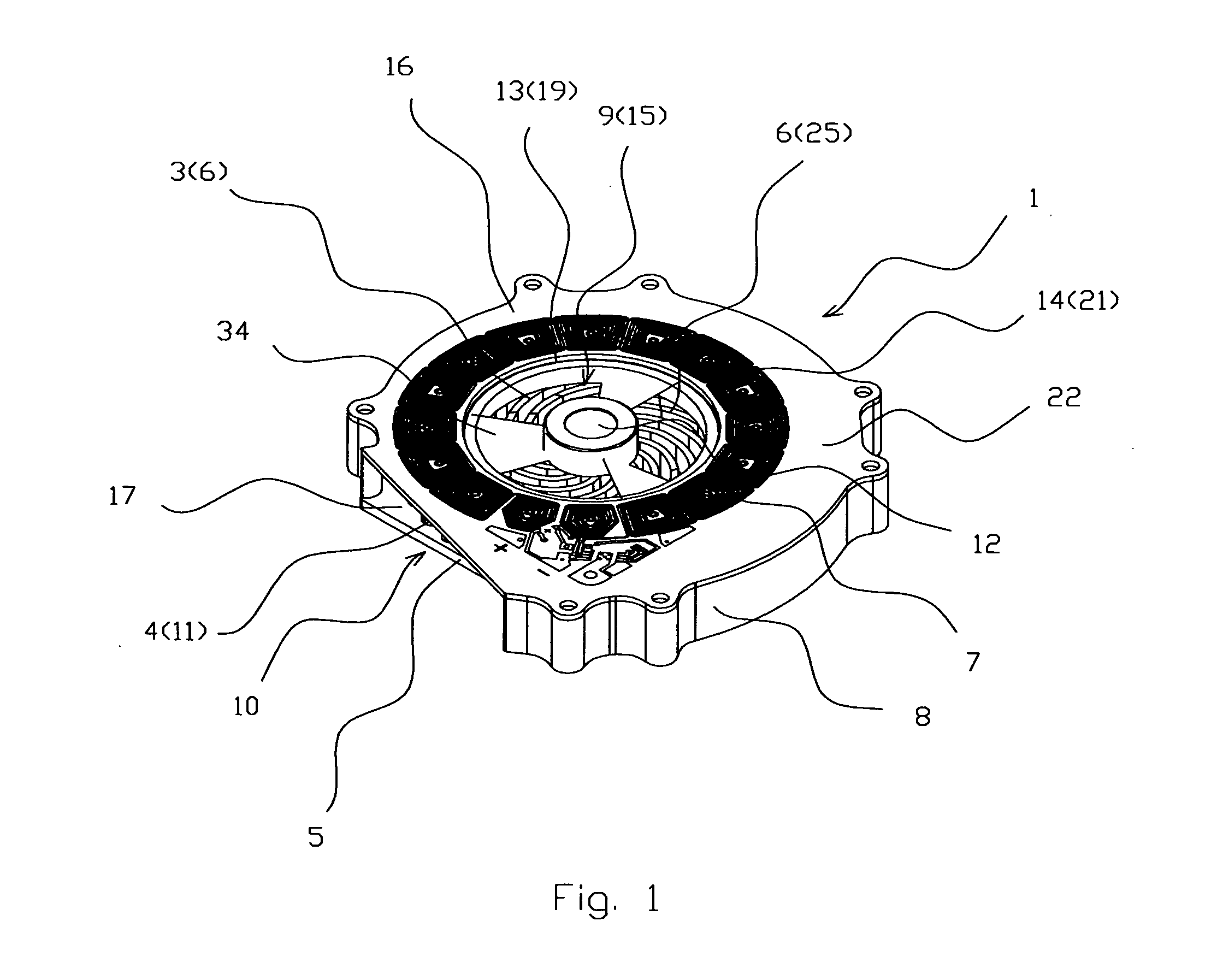
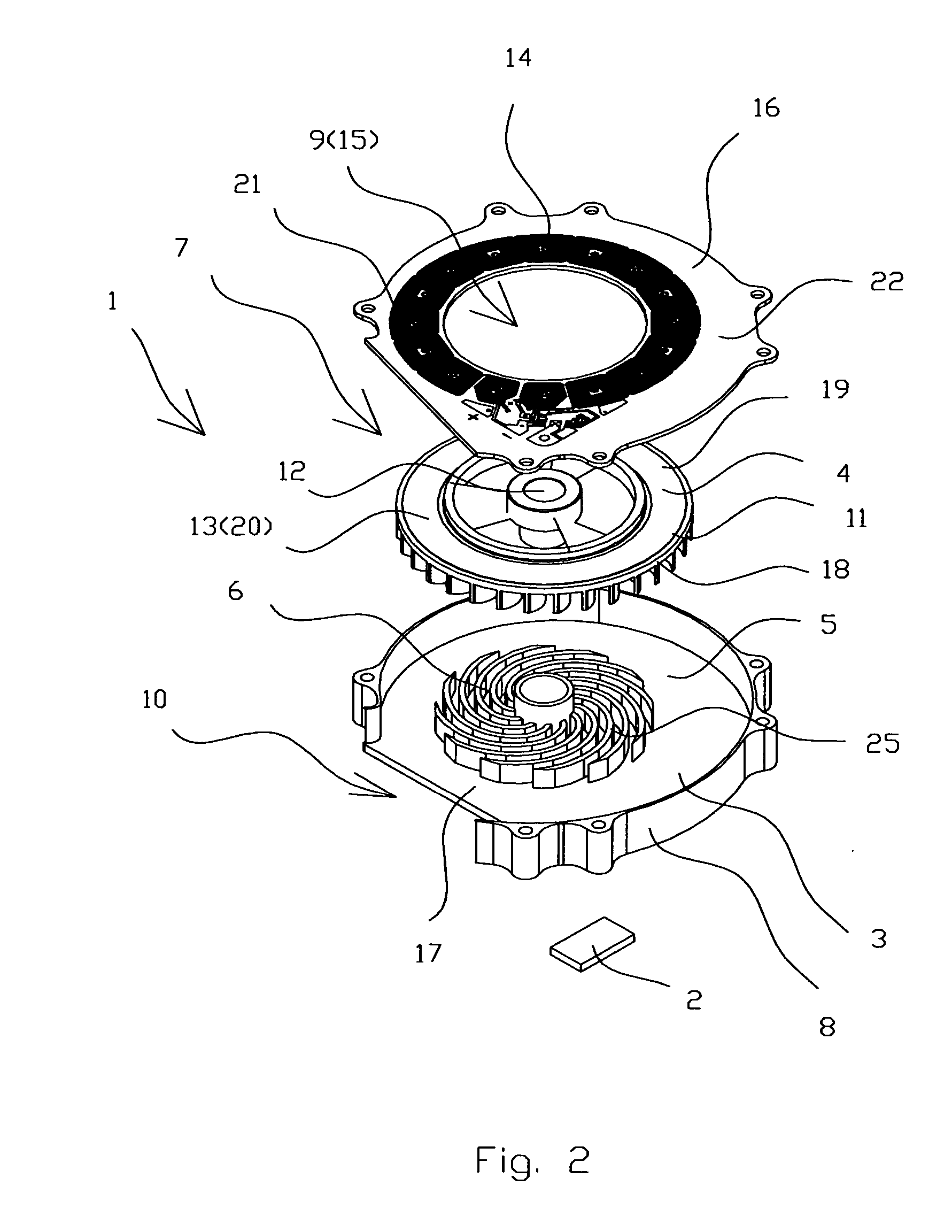
[0035] The integrated cooler 1 for electronic devices 2 (FIGS. 1-4 and 6-12) comprises a heatsink 3 integrated with a centrifugal blower 4. The heatsink 3 comprises a base 5 and heat exchanging means 6. The centrifugal blower 4 comprises an electric motor 7, a casing 8 with inlet 9 and at least one outlet 10, a radial impeller 11 and an axle 12. The electric motor 7 comprises a magnetized rotor 13 and a flat stator 14 with an opening 15 coincided with blower inlet 9 thus the stator 14 serves as an upper side 16 of the casing 8. The base 5 made as a lower side 17 of the casing 8 and provides thermal contact with the electronic device 2 and the heat exchanging means 6. The impeller 11 comprise...


PUM


Abstract

An integrated cooler comprises a heatsink integrated with a centrifugal blower. The heatsink comprises a base and heat exchanging means. The centrifugal blower comprises an electric motor, a casing with inlet and at least one outlet, a radial impeller and an axle. The electric motor comprises a magnetized rotor and a flat stator with an opening coincided with blower inlet thus the stator serves as an upper side of the casing. The base made as a lower side of the casing and provides thermal contact with the electronic device and the heat exchanging means. The radial impeller comprises magnetic means thus serving as the magnetized rotor. The heat exchanging means located inside of the radial impeller and surrounded by the blades thus cooling gas flows through the blower inlet, the heat exchanging means, the radial impeller and the at least one blower outlet in a series way.

Description

CROSS REFERENCE TO RELATED APPLICATIONS [0001] The present application claims the benefit of priority of U.S. Provisional Patent Application No. 60 / 591,492, filed Jul. 27, 2004 for Edward Lopatinsky at al. the entire content of which is incorporated herein by reference.FIELD OF THE INVENTION [0002] The present invention relates generally to cooling systems. More particularly, the present invention relates to cooling systems for regulating the temperature of electronic components. The present invention is particularly, but not exclusively, useful for a cooling system for regulating the temperature of electronic components of a Graphic Processor Unit (GPU). BACKGROUND OF THE INVENTION [0003] The regulation of the temperature due to heat generated inside the housing of an electronic device like GPU is an important consideration during the design of an electronic device. Cooling is important because if left unchecked, heat can cause electronic devices to malfunction during use or lead t...

Claims


Application Information

Patent Timeline
Patent Type & Authority Applications(United States)
IPC IPC(8): H05K7/20
CPCH01L23/467H01L2924/0002H01L2924/00
Inventor LOPATINSKY, EDWARDFEDOSEYEV, LEV
Owner INDAL DESIGN LAB
Why Eureka
Try Eureka