Vacuum belt conveyor system

Active Publication Date: 2006-02-02
SHERWOOD BERNARD J
View PDF6 Cites 33 Cited by
  • Summary
  • Abstract
  • Description
  • Claims
  • Application Information

AI Technical Summary

Benefits of technology

[0056] Owing to the individual sensing jets of both the suction and the blower block modules, air consumption is minimized, as air pressure is applied to each of the multi-stage vacuum-creating ejectors and to each blower block only when the presence of the transported sheet

Problems solved by technology

Prior systems, which monitor travel of the conveyor belt for such location purposes by encoding the revolutions of the driving motor, and which drive from an end roller, suffer from inaccuracy, due to belt slippage which generates discrepancies between rotation of the driving motor and the actual travel of the belt.
Inconsistencies in belt tension, with consequent variations in the rates of belt slippage, exacerbate this problem.
Certain types of article, for example lightweight articles having relatively large surface areas, such as plastic sheets, sheets of thin metal, cardboards, including cardboard blanks and blocks generally have smooth, low friction surfaces that make their transfer and handling most difficult.
In some instances, such problems are accentuated, due to the relative fragility of the articles, or other factors such as a susceptibility to becoming marked on their surfaces, as a consequence of transfer to or passage along a conveyor, including encounter with hard stops and position sensing mechanical feelers.
The response times of such systems is unduly slow, while the necessary air displacement is large, and excessive forces may be generated against system compo

Method used


Image

  • Vacuum belt conveyor system
  • Vacuum belt conveyor system
  • Vacuum belt conveyor system

Examples


Embodiment Construction

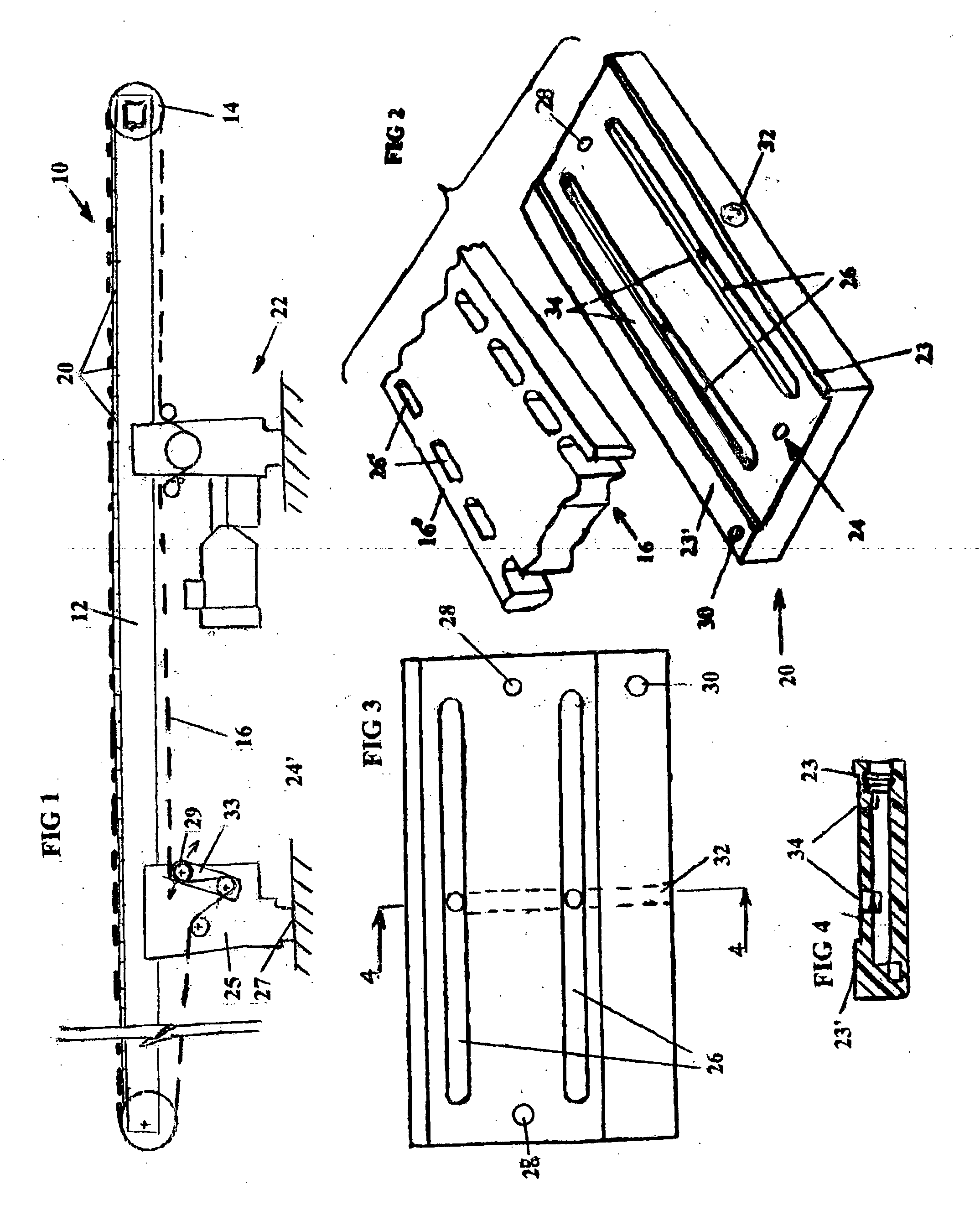
[0079] Referring to FIG. 1, the conveyor, 10 has an extended beam 12 of extruded aluminum section, a first embodiment being typically an 80×80 m.m section (see FIGS. 7 & 8) that runs the length of the conveyor 10. A second embodiment of a beam section is shown in FIG. 7A (to a smaller scale), having four significantly larger galleries. An on-going end roll 14 and an off-going end roll 14′ are mounted at the ends of the beam 12, about which rolls 14, 14′ an endless perforated conveyor belt 16 is trained (see FIGS. 5 and 6).

[0080] A location encoder 15 is driven by one of the end rolls, shown as being the ongoing roll. A series of vacuum blocks 20 extend the length of the conveyor 10, being mounted upon the beam 12.

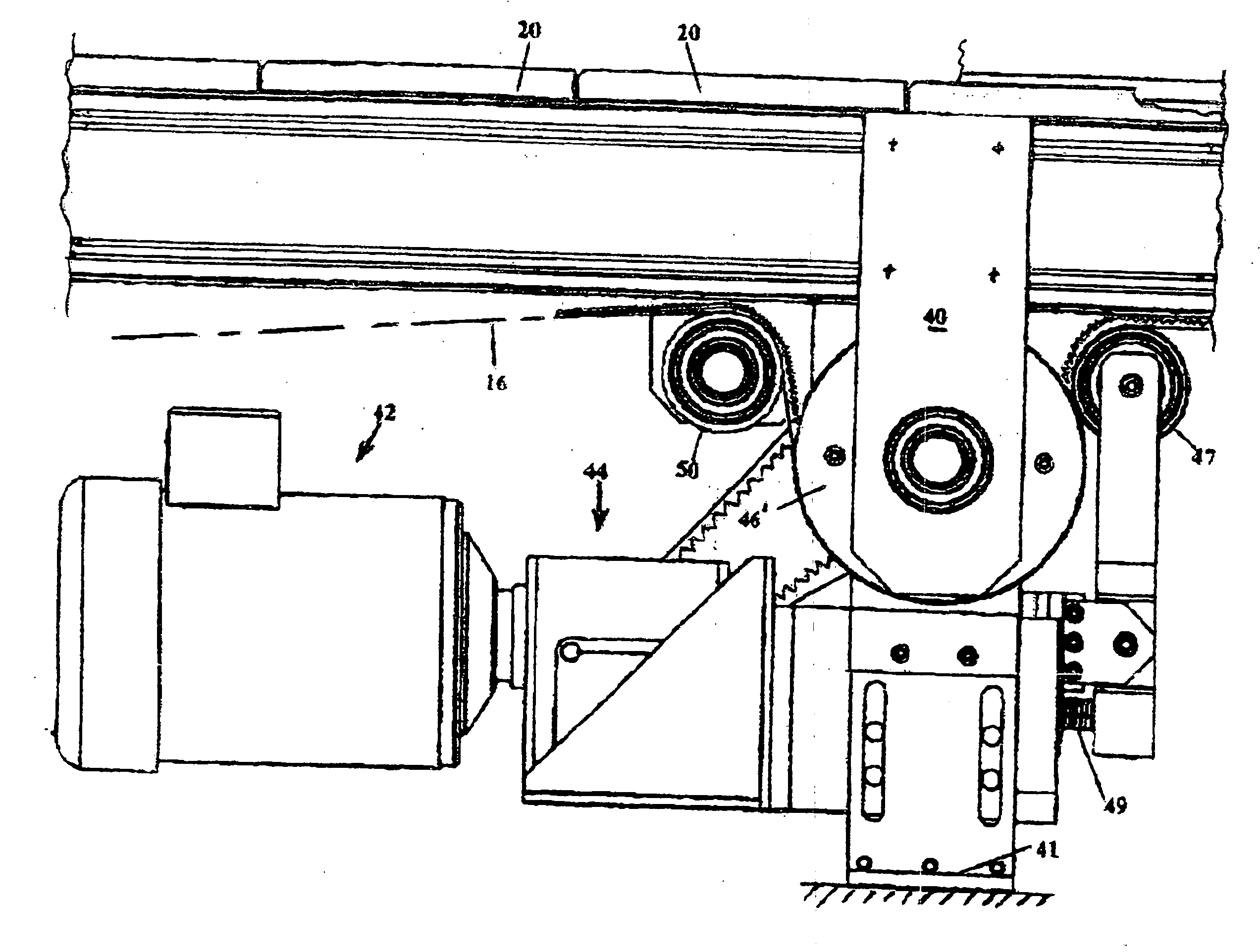
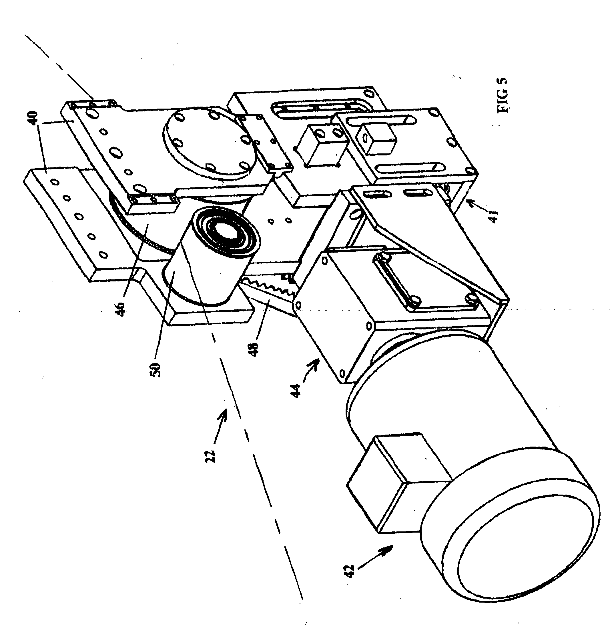
[0081] A belt drive 22 is located beneath the beam 12, in supporting relation therewith, being positioned in the mid-section of the conveyor 10, in spaced relation from the end rolls. The belt 16 is entrained with the belt drive 22.

[0082] The other end of the conveyor 12...


PUM


Abstract

A vacuum conveyor has a toothed belt with opposed sets of teeth along the sides of the belt inner surface; the belt is driven by a synchronous motor giving very precise delivery, the motor driving a toothed roll located in the conveyor centre section within the loop of the belt. The oncoming and offgoing belt guidance rolls have replaceable bearing inserts; two rolls control the wrap and load transfer between the belt and the driving roll; the top reach of the perforated belt slides on plastic vacuum blocks, having through air passages in corresponding patterned relation at the surfaces of the blocks, bounded by air-sealing shoulder portions of the blocks.

Description

CROSS-REFERENCE TO RELATED APPLICATIONS [0001] N.A. (Not Applicable) STATEMENT REGARDING FEDERALLY SPONSORED RESEARCH OR DEVELOPMENT [0002] N.A. REFERENCE TO A SEQUENCE LISTING, A TABLE, OR A COMPUTER PROGRAM LISTING [0003] N.A. COMPACT DISC APPENDIX [0004] N.A. BACKGROUND OF THE INVENTION [0005] 1. This invention is directed to a belt conveyor system, and in particular to an improved conveyor system incorporating a vacuum belt for effecting the pneumatic transfer of articles. [0006] 2. Belt conveyors for transferring articles are widely used in industry, including incorporation as integral parts of production lines, for a wide range of products. Such production lines frequently have work stations at spaced intervals, at which the conveyor is required to stop, to enable working upon the conveyed article. In such instances the precise monitoring of the displacement of the conveyor belt along its path and the lateral, horizontal positioning of the conveyed articles becomes very import...

Claims


Application Information

Patent Timeline
IPC IPC(8): B65G23/44
CPCB65G15/58B65G2203/042B65G2201/022
Inventor SHERWOOD, BERNARD J.
Owner SHERWOOD BERNARD J
Why Eureka
Try Eureka