Continuous ammonium removal systems

a technology of ammonium removal and ammonium sludge, which is applied in the direction of water/sewage treatment by ion exchange, nuclear engineering, and sedimentation settling tanks, etc. it can solve the problems of affecting the effect of reducing the amount of toxic sludge produced by biological processes, affecting the effect of reducing the amount of toxic sludge, and limiting the effectiveness of biological systems

Inactive Publication Date: 2006-02-02
NEW EARTH SYST
View PDF27 Cites 22 Cited by
  • Summary
  • Abstract
  • Description
  • Claims
  • Application Information

AI Technical Summary

Benefits of technology

[0014] It has been recognized that it would be advantageous to develop a wastewater treatment system which solves the aforementioned problems. The present invention provides an effective system for addressing many of the difficulties encountered in wastewater treatment.
[0016] More specifically, in one potential embodiment of the present invention, these phases can include the step of removing large solids from a wastewater influent stream by passing the influent wastewater stream through a series of screens to create a primary, screened wastewater stream. The primary wastewater stream can then be directed to an electrocoagulation unit. A variety of electrocoagulation unit configurations can be used in the present invention in order to remove and flocculate a wide variety of contaminants. Dissolved, colloidal, and emulsified contaminants can be removed from the primary, screened wastewater stream by applying an electrical current to the electrocoagulation unit to induce precipitation and flocculation resulting in a secondary wastewater stream. An optional flocculant maturation unit can be included to allow for further formation of larger particulates. Fine particulate matter and flocculants can then be removed by passing the secondary wastewater stream through one or more fine filters to create a wastewater stream contaminated substantially only by unfiltered organics. The organically contaminated wastewater stream can then be subjected to an advanced oxidation process to create a tertiary wastewater stream. The tertiary wastewater stream can then be contacted with zeolites, allowing an effective amount of reaction time with the zeolites to create a polished water stream. The polished water stream can then be exposed to ozone to create a final decontaminated or disinfected water stream. Periodically, under some conditions, the zeolites can be refreshed with a brine solution using a process which allows for continuous processing of wastewater streams.

Problems solved by technology

However, biological systems have certain limitations.
For instance, if the microorganisms contained in the lagoons are shocked or killed by environmental changes or introduction of other agents, it can take weeks to produce a healthy colony of treatment bacteria.
Furthermore, biological processes produce an enormous amount of toxic sludge (comprised largely of dead microorganisms and their waste products), which must be subsequently treated before disposal.
Additionally, due to the large costs and time involved in constructing the facilities necessary for biological systems, they must be planned out well in advance of the anticipated need and may not respond to short term increases in the need for water treatment.
While highly effective, chlorination has considerable drawbacks including the necessity of containing, transporting, and manipulating large quantities of potentially lethal chlorine.
Frequently, the expense of maintaining appropriate chlorination facilities and training qualified personnel are cost prohibitive for smaller wastewater treatment facilities.
Such treatments often create large amounts of residual sludge which must be disposed of.
Further, chemical treatments are not well suited to influents of highly variable compositions.

Method used


Image

  • Continuous ammonium removal systems
  • Continuous ammonium removal systems
  • Continuous ammonium removal systems

Examples


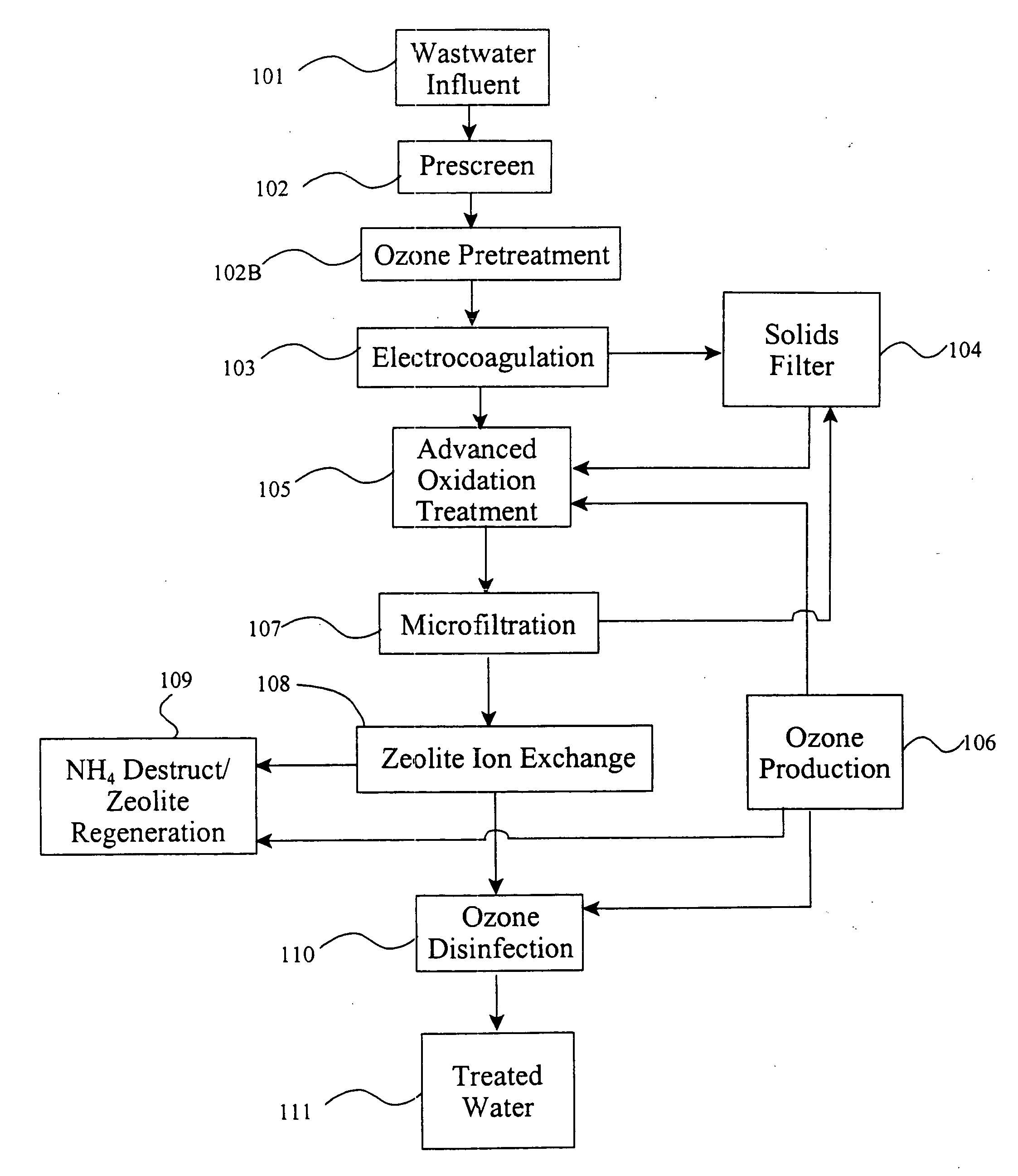
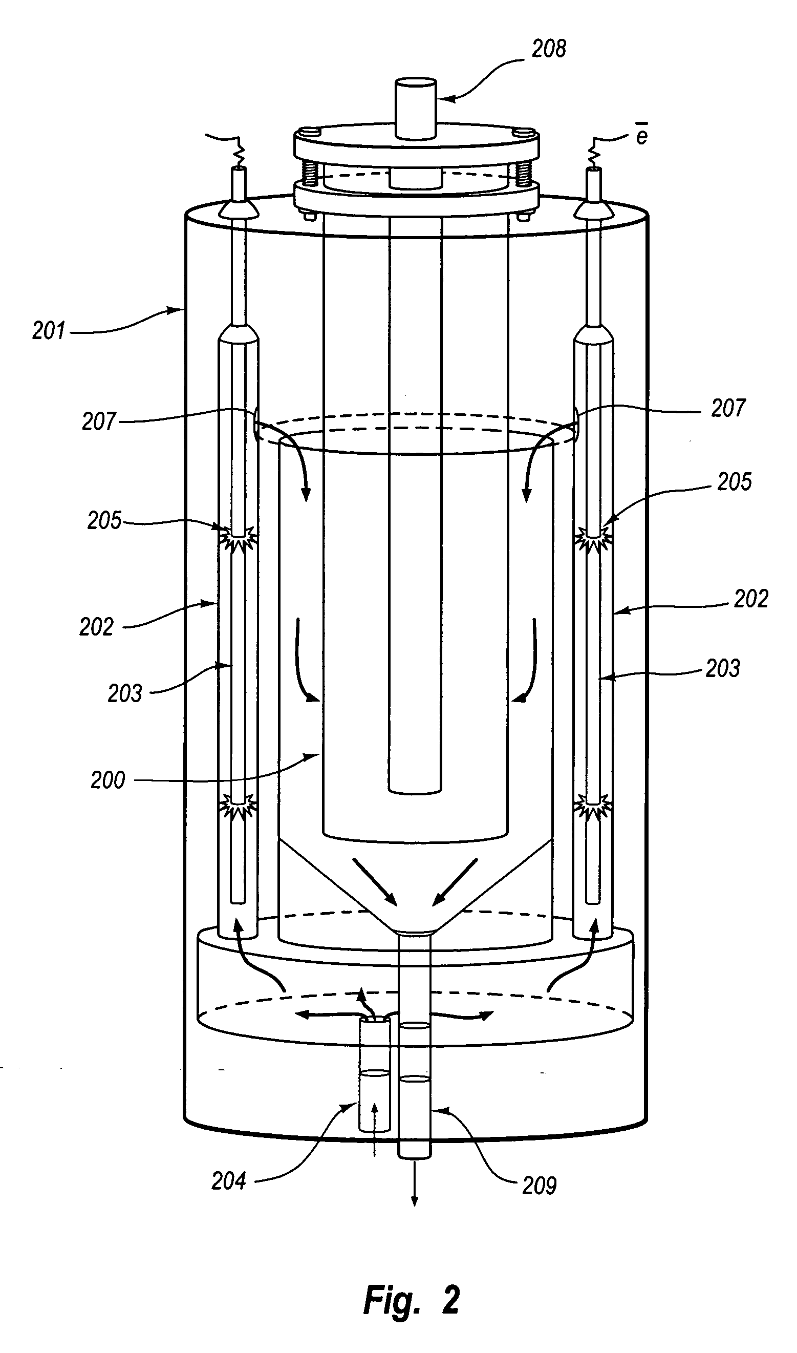
Embodiment Construction

[0026] Reference will now be made to the exemplary embodiments illustrated in the drawings, and specific language will be used herein to describe the same. It will nevertheless be understood that no limitation of the scope of the invention is thereby intended. Alterations and further modifications of the inventive features illustrated herein, and additional applications of the principles of the inventions as illustrated herein, which would occur to one skilled in the relevant art and having possession of this disclosure, are to be considered within the scope of the invention.

[0027] The singular forms “a,”“an,” and “the” include the plural referents unless the context clearly dictates otherwise. Thus, for example, reference to “a heat source” includes reference to one or more such heat sources.

[0028] As used herein, “effective amount” refers to the minimal amount of a substance, agent, action, or time period to achieve a desired effect. For example, an effective amount of “cooling”...


PUM

PropertyMeasurementUnit
DC voltageaaaaaaaaaa

Abstract

A continuous ammonium removal system comprising generally an ion-exchange medium, a brine source, and an oxidative reactor. The reactor can operate with ozone as an oxidant and bromide as an oxidation catalyst. Brine recycles continuously from the reactor to the ion-exchange medium for further ammonium removal. Modular components for inline static mixing, degassing, heat exchange, flow control and electrocoagulation affect ammonium removal from waste water.

Description

PRIORITY CLAIM [0001] This application is a divisional of application Ser. No. 10 / 389,414, filed Mar. 14, 2003, pending, which claims priority to provisional application No. 60 / 364,806, filed Mar. 15, 2002, the disclosure of which is incorporated herein by reference.BACKGROUND OF THE INVENTION [0002] 1. Field of the Invention [0003] The present invention relates to wastewater treatment systems. [0004] 2. Related Art [0005] As the world's population grows and reserve supplies of clean water dwindle, the treatment of wastewater is becoming an increasingly important concern worldwide. Beginning in 1972 with the Clean Water Act, the United States substantially increased government regulations on wastewater treatment. These regulations along with aging water infrastructure, global population shifts, and the time pressures of existing treatment facilities further highlight the growing pressures on wastewater treatment industry. [0006] Conventional wastewater treatment facilities employ a ...

Claims


Application Information

Patent Timeline
Patent Type & Authority Applications(United States)
IPC IPC(8): C02F1/42C02F1/78B01D15/04B01D17/06B01D21/00B01F5/00B01F5/04B01F5/06B01J39/14C02F1/00C02F1/20C02F1/44C02F1/463C02F1/72C02F9/00
CPCB01D17/0217B01D17/06C02F2201/008C02F2101/16C02F2001/425C02F9/00B01D21/0009B01D21/0012B01D21/08B01F5/0453B01F5/0465B01F5/0614B01F5/0659B01F2005/0017B01F2005/0632B01F2005/0637B01J39/14B01J49/0008B01J49/0069C02F1/001C02F1/008C02F1/20C02F1/42C02F1/444C02F1/463C02F1/72C02F1/78B01J49/06B01J49/53B01F2025/913B01F25/3132B01F25/313311B01F25/4314B01F25/43195B01F25/431972B01F25/435
Inventor BRADLEY, KIRK D.
Owner NEW EARTH SYST
Why Eureka
Try Eureka