Optical disk device recording data on a recordable or rewritable optical disk by setting a recording velocity and a recording power for each of zones on an optical disk

a technology of optical disk and recording power, which is applied in the direction of optical beam sources, recording signal processing, instruments, etc., can solve the problems of inability to increase the revolution of the disk, the inability to record data on the recordable or rewritable optical disk, and the inability to make the memory capacity larger, etc., to achieve the effect of high-quality recording

Inactive Publication Date: 2006-02-02
HAGIWARA KEI +1
View PDF13 Cites 7 Cited by
  • Summary
  • Abstract
  • Description
  • Claims
  • Application Information

AI Technical Summary

Benefits of technology

[0022] It is a general object of the present invention to provide an improved and useful optical disk device, an information processing device, an optical disk recording method, a constant estimating method, and an information recording device in which the above-mentioned problems are eliminated.
[0023] A more specific object of the present invention is to provide an optical disk device, an information processing device, an optical disk recording method, a constant estimating method, and an information recording device which can effectively shorten an average recording time by increasing an average recording velocity even in a data-recording requiring a continuity, can curb the amount of electric power consumed during a data-recording, can perform a stable data-reproduction after a data-recording for each zone on an optical disk by appropriately adjust a recording power, can achieve an stable quality of a data-recording by maintaining a continuity of an interleave and a data row even at a boundary between zones on an optical disk, can achieve a further stable quality of a data-recording by maintaining a continuity of an interleave and a data row at a boundary between zones on an optical disk more accurately, and can accurately determine a recording power and other recording conditions even at a linear velocity different from a linear velocity in a test-writing so as to perform a high-quality recording even at a high-speed area.

Problems solved by technology

As for the optical disk of the format of the CAV type, although it is easy to control the revolution of the disk during a data-recording and a data-reproducing, there is an inconvenience that a density is low at an outer periphery of the disk, and thus a memory capacity cannot be made larger.
However, as shown in FIG. 2-(a), in the CLV method, since the revolutions of the disk are large in number at the inner periphery of the optical disk, there is an inconvenience that the revolutions of the disk cannot be increased due to a limit of a revolving system at the inner periphery of the optical disk; thus the recording velocity cannot be increased.
Inconveniences of the revolving system include not only a limitation due to a mechanical requirement for a high torque, but also an increase in an amount of electric power to be consumed in a spindle motor and a motor driver thereof.
However, the data-recording by the CAV method is not used in general very much, because there are many problems as follows: a laser power required for a data-recording becomes larger as the data-recording proceeds toward the outer periphery of the optical disk, making the control thereof difficult; a recording signal frequency varies continuously within the optical disk, complicating the generation of a recording pulse; etc.
Since a certain amount of time is generally required to stabilize a revolving system of the optical disk, changing the recording velocity sharply during a data-recording may possibly deteriorate the quality of a signal at the recorded part and thus disable the reproduction thereof.
Further, conventionally, since a pause during a data-recording is not allowed to be performed, a data-writing unit becomes large to a certain extent.
Therefore, when a transfer of record data from a host computer cannot keep up with the recording velocity, a recording error called buffer-underrun occurs.
However, in the CLV method, as the recording is performed nearer the inner periphery, the revolution of the disk needs to be made faster, i.e., the angular velocity of the disk needs to be made higher, making it difficult to revolve the disk at such a high speed.
This leads to a higher cost of a motor and the increase in noises and vibrations; it also becomes difficult to design other servo systems.
However, the above-mentioned conventional information recording devices cannot perform a high-quality recording unless recording characteristics (i.e., a necessary recording power and other recording conditions) of the disk-type recording medium are completely in proportion with the linear velocity.

Method used


Image

  • Optical disk device recording data on a recordable or rewritable optical disk by setting a recording velocity and a recording power for each of zones on an optical disk
  • Optical disk device recording data on a recordable or rewritable optical disk by setting a recording velocity and a recording power for each of zones on an optical disk
  • Optical disk device recording data on a recordable or rewritable optical disk by setting a recording velocity and a recording power for each of zones on an optical disk

Examples


embodiment 1

[0162] [Embodiment 1]

[0163] A description will now be given of a first embodiment according to the present invention.

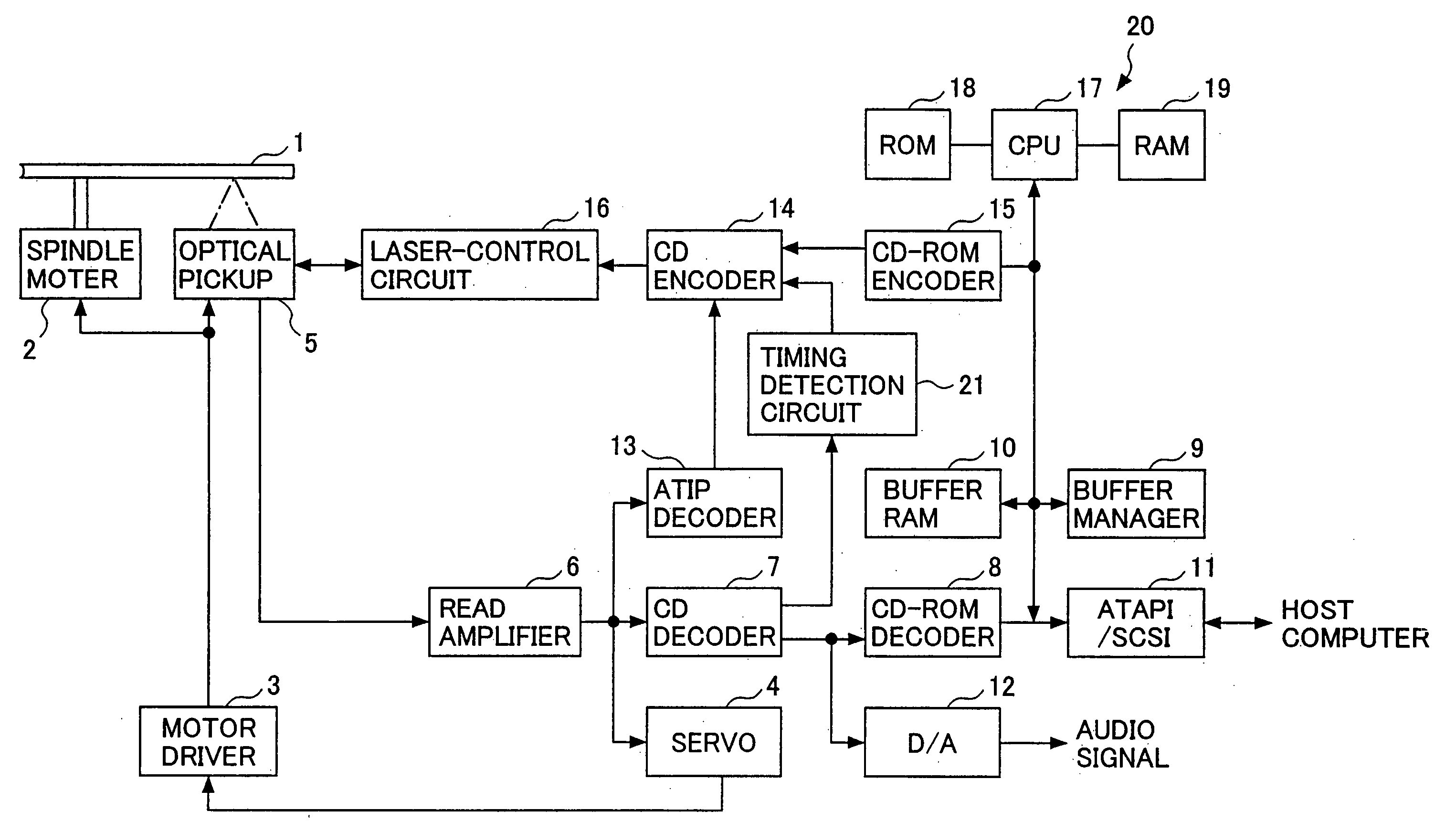
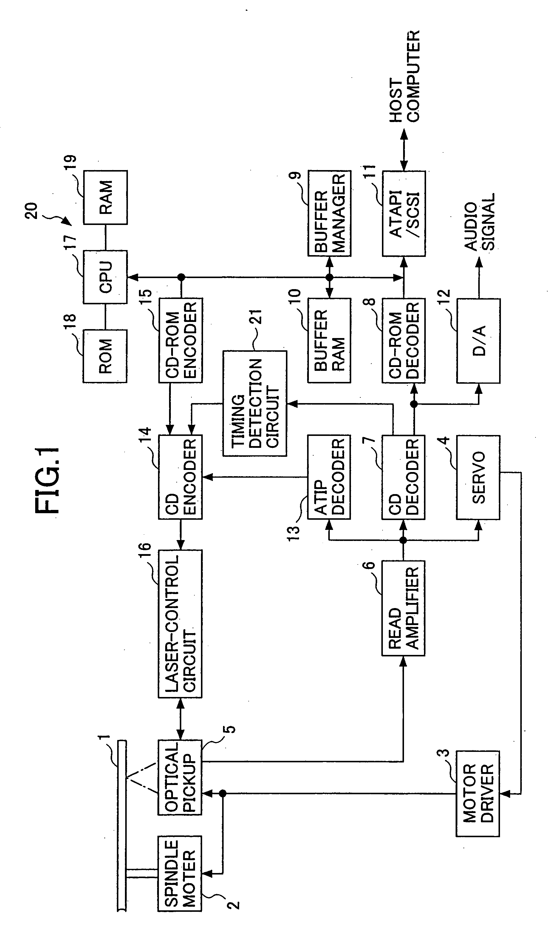
[0164]FIG. 1 is a block diagram showing a structure of an optical disk device according to a first embodiment of the present invention. This optical disk device can record data to a CD-R / RW (CD-Recordable / Rewritable).

[0165] As shown in FIG. 1, an optical disk 1 is revolved by a spindle motor 2. The spindle motor 2 is controlled by a motor driver 3 and a servo means 4 so that the spindle motor 2 revolves the optical disk 1 by a CLV (Constant Linear Velocity) method.

[0166] Next; an optical pickup 5 can project a laser beam from a laser beam source such as a laser diode and can converge the laser beam on a recording surface of the optical disk 1 by an objective lens. The optical pickup 5 can reproduce data from and record data to the optical disk 1 by controlling an actuator by using a focus servo and a track servo.

[0167] In reproducing data, a reproduction signal ob...

embodiment 2

[0200] [Embodiment 2]

[0201] A description will now be given of a second embodiment according to the present invention.

[0202] In the following description, elements that are identical or equivalent to the elements described in the first embodiment are referenced by the same reference marks, and will not be described in detail.

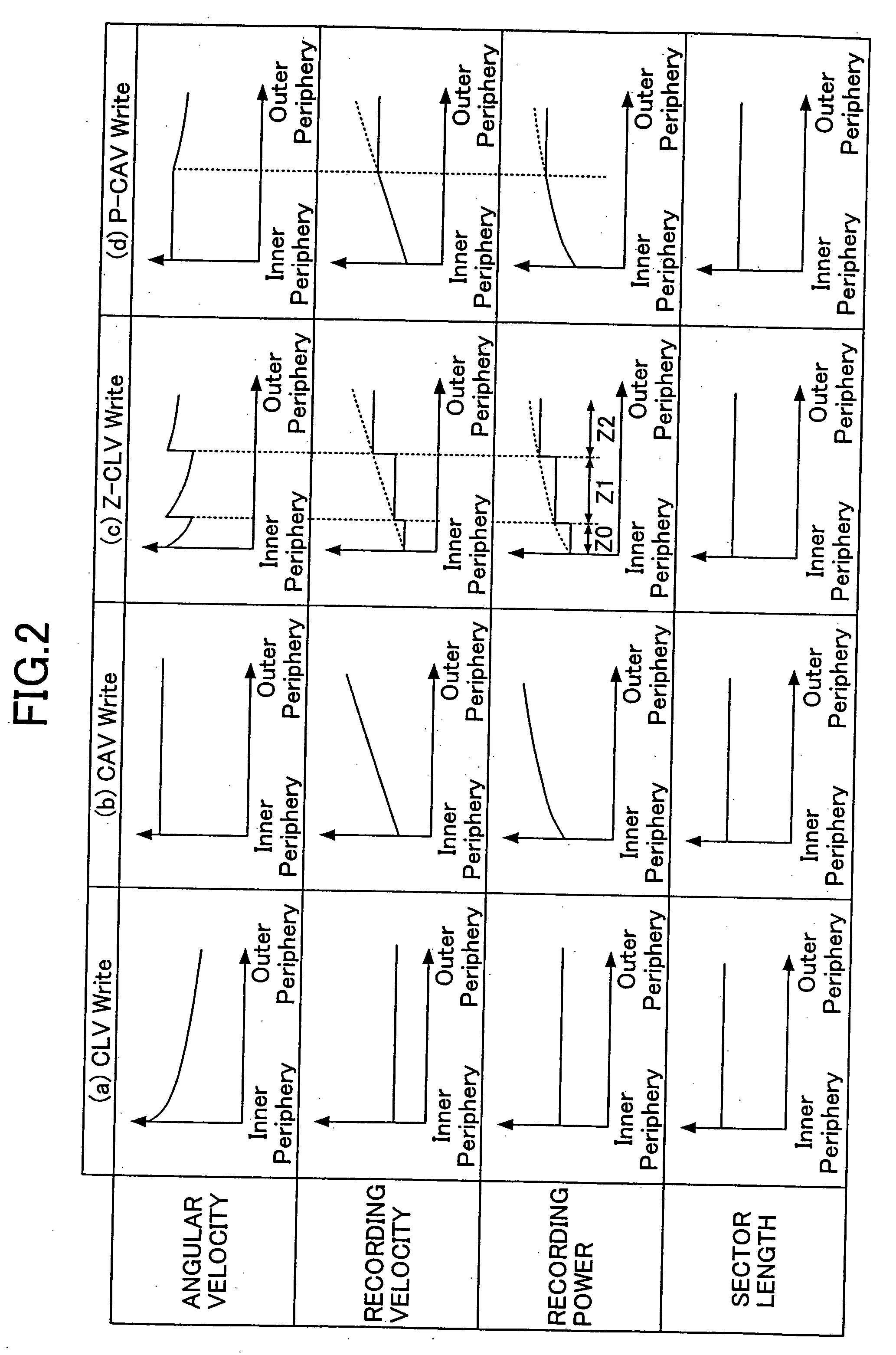
[0203] The second embodiment differs from the first embodiment in that a format is of a TAO (Track at once) or SAO (Session at once) recording, in which a data-recording is so performed as to finish a recording of one track or one session at one time, and by considering the track or the session of this case as one zone, the data-recording of the Z-CLV method is performed. Therefore, the ROM 18, etc. preliminarily stores position information of zones, by recognizing a boundary between tracks on the optical disk 1 as a boundary between the zones, in the case of TAO, and by recognizing a boundary between sessions on the optical disk 1 as a boundary between the zo...

embodiment 3

[0210] [Embodiment 3]

[0211] A description will now be given of a third embodiment according to the present invention.

[0212] In the following description, elements that are identical or equivalent to the elements described in the first embodiment are referenced by the same reference marks, and will not be described in detail.

[0213] The third embodiment differs from the first embodiment in that a packet write is used as a format (the format is shown in FIG. 14) so as to perform a data-recording in which a recording of one packet is finished at one time, and, in this case, the Z-CLV method is realized by having a Link sector of a packet as a boundary between zones.

[0214] When a data-recording is performed in packet-writing, if a boundary between zones assumed by the optical disk device falls on the middle of packet data, changing the recording velocity by pausing / restarting at that point is not effective in terms of a recording time.

[0215] Thereupon, since a packet length has a lim...


PUM

PropertyMeasurementUnit
velocityaaaaaaaaaa
recording poweraaaaaaaaaa
recording powersaaaaaaaaaa

Abstract

An optical disk device records data on a recordable or rewritable optical disk. The optical disk device comprises zone storing means for preliminarily storing locations of a plurality of zones set by dividing a recordable or rewritable area of the optical disk from an inner periphery thereof to an outer periphery thereof, position detecting means for detecting a position on the optical disk so as to record data at the position, judging means for judging which of the zones the position corresponds to by referring to the zone storing means, and controlling means for controlling the device to perform a data-recording by a CLV method to each of the zones specified by the judging means by setting a recording velocity and a recording power for each of the zones so as to enable the data-recording to provide an equal recording density to all of the zones.

Description

BACKGROUND OF THE INVENTION [0001] 1. Field of the Invention [0002] The present invention generally relates to an optical disk device, an information processing device, an optical disk recording method, a constant estimating method, and an information recording device, and more particularly, to an optical disk device, an information processing device, an optical disk recording method, a constant estimating method, and an information recording device which record data on a disk-type recording medium, such as a recordable or rewritable optical disk. [0003] 2. Description of the Related Art [0004] It is well known that recording formats for an optical disk include a CLV (Constant Linear Velocity) type in which a data row (a data train) on an optical disk is at a constant velocity when viewed from an optical pickup, and a CAV (Constant Angular Velocity) type in which an angular velocity of an optical disk is constant. [0005] As for the optical disk of the format of the CAV type, althoug...

Claims


Application Information

Patent Timeline
Patent Type & Authority Applications(United States)
IPC IPC(8): G11B7/00G11B7/12G11B7/0045G11B7/007G11B7/125G11B20/12G11B27/36
CPCG11B7/0045G11B2220/2545G11B7/0079G11B7/126G11B7/1267G11B19/26G11B20/1217G11B20/1258G11B27/36G11B2020/1235G11B2020/1238G11B2020/1244G11B2020/1245G11B2020/1275G11B2020/1277G11B2020/1297G11B2220/215G11B2220/216G11B2220/218G11B2220/2537G11B7/007
Inventor HAGIWARA, KEISUZUKI, HARUYUKI
Owner HAGIWARA KEI
Why Eureka
Try Eureka