Optical disk device recording data on a recordable or rewritable optical disk by setting a recording velocity and a recording power for each of zones on an optical disk
a technology of optical disk and recording power, which is applied in the direction of digital signal error detection/correction, instruments, recording signal processing, etc., can solve the problems of inability to increase the revolution of the disk, the inability to increase the recording speed, and the inability to increase the memory capacity
- Summary
- Abstract
- Description
- Claims
- Application Information
AI Technical Summary
Benefits of technology
Problems solved by technology
Method used
Image
Examples
embodiment 1
[0164][Embodiment 1]
[0165]A description will now be given of a first embodiment according to the present invention.
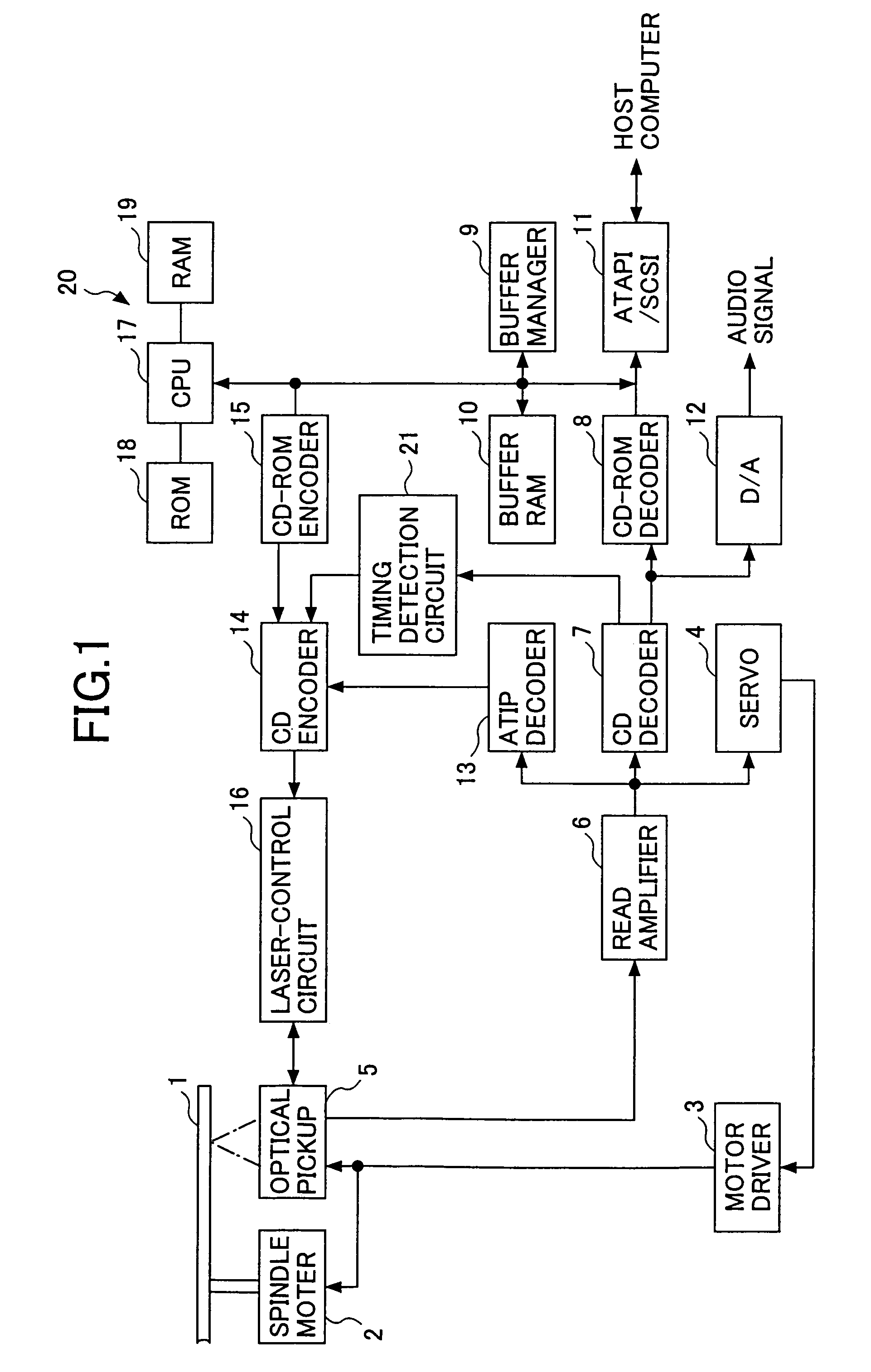
[0166]FIG. 1 is a block diagram showing a structure of an optical disk device according to a first embodiment of the present invention. This optical disk device can record data to a CD-R / RW (CD-Recordable / Rewritable).
[0167]As shown in FIG. 1, an optical disk 1 is revolved by a spindle motor 2. The spindle motor 2 is controlled by a motor driver 3 and a servo means 4 so that the spindle motor 2 revolves the optical disk 1 by a CLV (Constant Linear Velocity) method.
[0168]Next, an optical pickup 5 can project a laser beam from a laser beam source such as a laser diode and can converge the laser beam on a recording surface of the optical disk 1 by an objective lens. The optical pickup 5 can reproduce data from and record data to the optical disk 1 by controlling an actuator by using a focus servo and a track servo.
[0169]In reproducing data, a reproduction signal obtained by...
embodiment 2
[0203][Embodiment 2]
[0204]A description will now be given of a second embodiment according to the present invention.
[0205]In the following description, elements that are identical or equivalent to the elements described in the first embodiment are referenced by the same reference marks, and will not be described in detail.
[0206]The second embodiment differs from the first embodiment in that a format is of a TAO (Track at once) or SAO (Session at once) recording, in which a data-recording is so performed as to finish a recording of one track or one session at one time, and by considering the track or the session of this case as one zone, the data-recording of the Z-CLV method is performed. Therefore, the ROM 18, etc. preliminarily stores position information of zones, by recognizing a boundary between tracks on the optical disk 1 as a boundary between the zones, in the case of TAO, and by recognizing a boundary between sessions on the optical disk 1 as a boundary between the zones, i...
embodiment 3
[0213][Embodiment 3]
[0214]A description will now be given of a third embodiment according to the present invention.
[0215]In the following description, elements that are identical or equivalent to the elements described in the first embodiment are referenced by the same reference marks, and will not be described in detail.
[0216]The third embodiment differs from the first embodiment in that a packet write is used as a format (the format is shown in FIG. 14) so as to perform a data-recording in which a recording of one packet is finished at one time, and, in this case, the Z-CLV method is realized by having a Link sector of a packet as a boundary between zones.
[0217]When a data-recording is performed in packet-writing, if a boundary between zones assumed by the optical disk device falls on the middle of packet data, changing the recording velocity by pausing / restarting at that point is not effective in terms of a recording time.
[0218]Thereupon, since a packet length has a limit, a cert...
PUM
 Abstract
Description
Claims
Application Information
 - R&D
- Intellectual Property
- Life Sciences
- Materials
- Tech Scout
- Unparalleled Data Quality
- Higher Quality Content
- 60% Fewer Hallucinations
Browse by: Latest US Patents, China's latest patents, Technical Efficacy Thesaurus, Application Domain, Technology Topic, Popular Technical Reports.
© 2025 PatSnap. All rights reserved.Legal|Privacy policy|Modern Slavery Act Transparency Statement|Sitemap|About US| Contact US: help@patsnap.com


