Optical add/drop multiplexer

a technology of optical add/drop multiplexer and optical network, applied in multiplex communication, electromagnetic repeater, instruments, etc., can solve the problems of difficult to construct flexible oadm nodes, complicated management of ports and signal light wavelengths, and conventional optical add/drop multiplexers, etc., to achieve the effect of increasing the transmission distance between nodes on the optical network and small and cheap optical add/drop multiplexers

Inactive Publication Date: 2006-02-02
FUJITSU LTD
View PDF10 Cites 18 Cited by
  • Summary
  • Abstract
  • Description
  • Claims
  • Application Information

AI Technical Summary

Benefits of technology

[0016] In the optical add/drop multiplexer of the invention, it is sufficient to dispose one amplifying part to realize addition, drop, and through of signal light having a specific wavelength to/from WDM light input from a

Problems solved by technology

The conventional optical add/drop multiplexer, however, has the following problems.
In the configuration in which two AWGs are combined as shown in FIG. 24, since the input/output wavelength characteristics of each of the ports of the AWG are fixed, when the number of wavelengths of signal light to be processed increases, management of the ports and the signal light wavelengths becomes complicated, and a problem occurs such that it is difficult to construct a flexible OADM node.
Since an optical amplifier for compensating a loss in the two AWGs, the optical branch couplers, the 2×1 optical switches, and the like has to be provided for each of the input and output stages, there are also problems such that the size of the multiplexer becomes large and the cost increases.
However, the AOTF is

Method used


Image

  • Optical add/drop multiplexer
  • Optical add/drop multiplexer
  • Optical add/drop multiplexer

Examples


first embodiment

[0046]FIG. 3 is a block diagram showing the configuration of an optical add / drop multiplexer according to the invention.

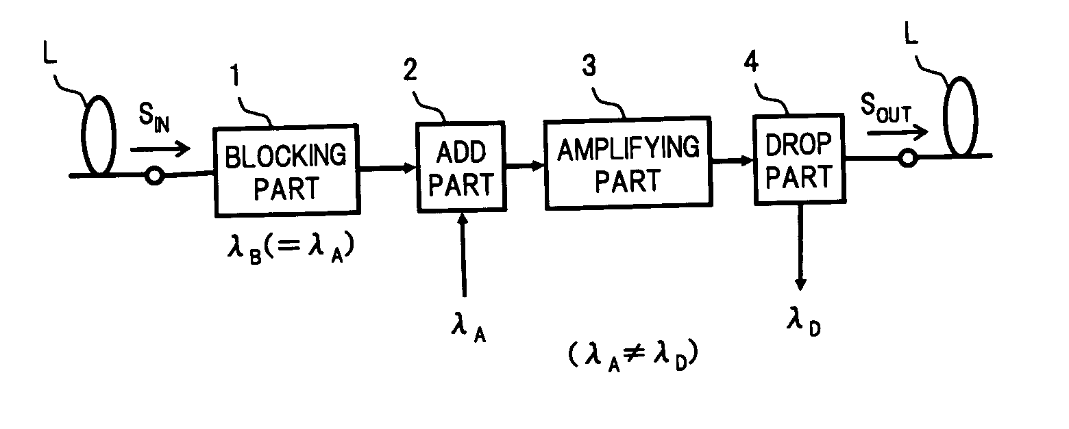
[0047] In FIG. 3, an optical add / drop multiplexer of the embodiment has, for example, a wavelength blocker (WB) 11 as the blocking unit 1 in the basic configuration shown in FIG. 1, an optical coupler (CPL) 21 and a WDM coupler 22 as the inserting unit 2, a WDM optical amplifier 31 as the amplifying unit 3, and an optical branch coupler (CPL) 41 and an optical filter circuit 42 as the dropping unit 4.

[0048] WDM light SIN propagating through a transmission line L of an optical network constructing an OADM node by using the optical add / drop multiplexer is supplied to the input port of the wavelength blocker 11. The wavelength blocker 11 is a known optical device of blocking passage of light in a wavelength band which is preliminarily selected for input light and passing and outputting the other light from the output port. In the following, the wavelength bandwidth o...

second embodiment

[0059] the invention will now be described.

[0060]FIG. 5 is a block diagram showing the configuration of an optical add / drop multiplexer according to a second embodiment of the invention.

[0061] In FIG. 5, the different part of the configuration of the optical add / drop multiplexer of the second embodiment from that of the first embodiment (FIG. 3) is that a rejection add filter 12 is provided in place of the wavelength blocker 11 and the optical coupler 21 used in the first embodiment. Since the other configuration is similar to that of the first embodiment, its description will not be repeated.

[0062] The rejection add filter 12 is a known optical filter having, for example, as shown in (A) of FIG. 6, three ports; a common port P1, an add port P2, and a reflection port P3 and realizing, as shown in (B) of FIG. 6, by a thin film filter (TFF) internally provided, a transmission (or reflection) wavelength characteristic from the common port P1 to the reflection port P3 and a transmissi...

third embodiment

[0065]FIG. 7 is a block diagram showing the configuration of an optical add / drop multiplexer according to the invention.

[0066] A feature of the optical add / drop multiplexer shown in FIG. 7 is that a variable optical branch coupler 41′ whose branching ratio is variable is provided in place of the optical branch coupler 41 in the drop part in the first embodiment so that the power of the WDM light SIN and drop light transmitted to a node on the downstream can be controlled by adjusting the branching ratio of the variable optical branch coupler 41′ in accordance with setting of the wavelength of drop light or the like in the node. Another feature of the optical add / drop multiplexer is that a variable optical attenuator 24 is inserted at the former stage of a wavelength blocker 11′ so as to control the balance of the power of through light and add light multiplexed by the optical coupler 21.

[0067] Concretely, to handle a change in the setting of the wavelength of drop light, a 1×J opti...


PUM


Abstract

An optical add/drop multiplexer of the invention includes: a wavelength blocker for blocking signal light having at least one wavelength out of a plurality of signal lights included in WDM light supplied from a transmission line and passing the other signal light; an optical coupler for multiplexing signal light having the same wavelength as that of the signal light blocked by the wavelength blocker to signal light passed through the wavelength blocker; a WDM amplifier for amplifying the WDM light multiplexed by the optical coupler and outputting the amplified light; and an optical branch coupler for branching the WDM light output from the WDM amplifier into two lights, extracting signal light having at least one wavelength different from the wavelength of signal light multiplexed by the optical coupler from one of the branched lights, and outputting the other branched light to the transmission line. With the configuration, a small and cheap optical add/drop multiplexer as a flexible OADM node can be provided.

Description

BACKGROUND OF THE INVENTION [0001] (1) Field of the Invention [0002] The present invention relates to an optical add / drop multiplexer (OADM) of adding or dropping signal light having a specific wavelength from wavelength division multiplexed (WDM) light obtained by multiplexing a plurality of rays of signal light having different wavelengths and, more particularly, to an optical add / drop multiplexer constructed by using an optical amplifier. [0003] (2) Related Art [0004] As the configuration of one of conventional optical add / drop multiplexer, for example, as shown in FIG. 24, a configuration in which two arrayed waveguide gratings (AWG) 101A and 101B are combined is known. The AWGs 101A and 101B are devices having the optical multiplexing / demultiplexing function. When WDM light is input to the input port, light demultiplexed at each wavelength is output from each of the ports on the output side. On the other hand, when light having a predetermined wavelength is input to each of the...

Claims


Application Information

Patent Timeline
IPC IPC(8): G02B6/28H04B10/03H04B10/07H04B10/077H04B10/079H04B10/2525H04B10/27H04B10/29H04B10/296H04B10/40H04B10/50H04B10/60H04J14/00H04J14/02
CPCH04J14/0206H04J14/0212H04J14/0213H04J14/0297H04J14/0283H04J14/0286H04J14/022
Inventor NAKAGAWA, GOJIKAI, YUTAKA
Owner FUJITSU LTD
Why Eureka
Try Eureka