

Reciprocating compressor and manufacturing method thereof
- Summary
- Abstract
- Description
- Claims
- Application Information
AI Technical Summary
Benefits of technology
Problems solved by technology
Method used
Image

Examples
third embodiment
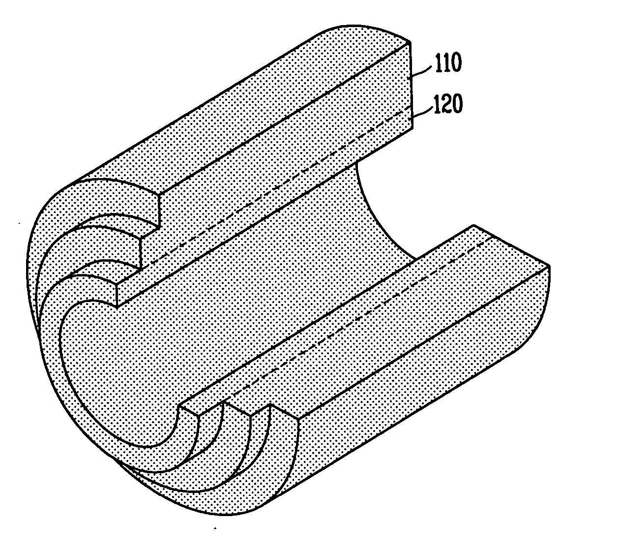
[0048] On the other hand, the inner stator 110 and the cylinder 120 can be individually manufactured by sintering magnetic metal powder or another metal powder, and bonded to each other by diffusion bonding. FIG. 7 is a cross-sectional diagram illustrating an inner stator and a cylinder of a reciprocating compressor in accordance with the present invention. As depicted in FIG. 7, the inner stator 110 and the cylinder 120 are individually manufactured, and the inner stator 110 is inserted onto the outer circumference of the cylinder 120.
[0049] The manufacturing method of the present invention will now be explained.
[0050] Generally, when magnetic metal powder is heated at a high temperature, the bonding strength of particles is improved to increase abrasion resistance. However, when the magnetic metal powder is heated at a high temperature over 500° C. in the sintering process, the magnetic metal powder may be demagnetized. It is thus very important to perform the sintering process w...
second embodiment
[0054]FIG. 9 is a block diagram illustrating the manufacturing method of the reciprocating compressor in accordance with the present invention.
[0055] As illustrated in FIG. 9, the inner stator 110 and the cylinder 120 are temporarily formed in a single form by supplying primary metal powder and secondary metal powder to a predetermined shape of die. The outside portion of the temporary product composing the inner stator 110 is heated and primarily sintered at a temperature of about 400° C., and the inside portion of the temporary product composing the cylinder 120 is locally heated and secondarily sintered at a temperature of about 1000° C. As a result, the inner stator 110 and the cylinder 120 are manufactured in a single form.
[0056]FIG. 10 is a block diagram illustrating the manufacturing method of the reciprocating compressor in accordance with the third embodiment of the present invention.
[0057] Referring to FIG. 10, the inner stator 110 and the cylinder 120 are temporarily fo...
fourth embodiment
[0058]FIG. 11 is a block diagram illustrating the manufacturing method of the reciprocating compressor in accordance with the present invention.
[0059] As shown in FIG. 11, the inner stator 110 and the cylinder 120 are individually manufactured by supplying primary metal powder and secondary metal powder to different dies, and heating and sintering the primary metal powder and the secondary metal powder at a necessary temperature for the inner stator 110 (about 400° C.) and a necessary temperature for the cylinder 120 (about 1000° C.), respectively. Thereafter, the inner stator 110 is bonded onto the outer circumference of the cylinder 120 by diffusion bonding.
[0060] As another example, although not illustrated, the inner stator 110 and the cylinder 120 are formed in a predetermined shape of die by using magnetic metal powder, and heated and sintered at a necessary temperature for the inner stator 110 (about 400° C.). An abrasion resistance coating surface can be formed on the inner...
PUM
| Property | Measurement | Unit |
|---|---|---|
| Temperature | aaaaa | aaaaa |
| Temperature | aaaaa | aaaaa |
| Temperature | aaaaa | aaaaa |
Abstract
Description
Claims
Application Information