HSQ/SOG dry strip process

Inactive Publication Date: 2006-02-02
TEXAS INSTR INC
View PDF5 Cites 70 Cited by
  • Summary
  • Abstract
  • Description
  • Claims
  • Application Information

AI Technical Summary

Benefits of technology

[0006] An advantage of the invention is providing an improved process for removing a spin-on dielectric that minimizes CD blowout.
[0007] This an

Problems solved by technology

As compared to the traditional subtractive plasma dry etching of aluminum, suitable copper etches for a semiconductor fabrication environment are not readily availabl

Method used


Image

  • HSQ/SOG dry strip process
  • HSQ/SOG dry strip process
  • HSQ/SOG dry strip process

Examples


Embodiment Construction

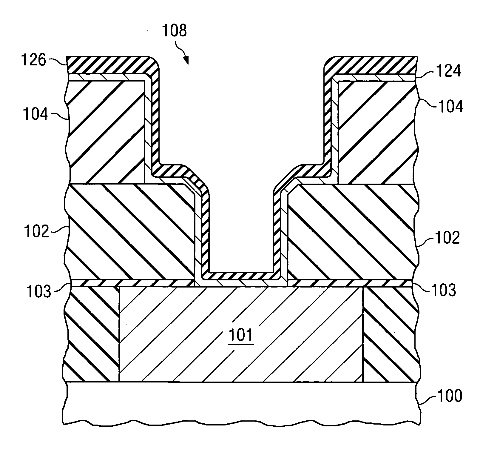
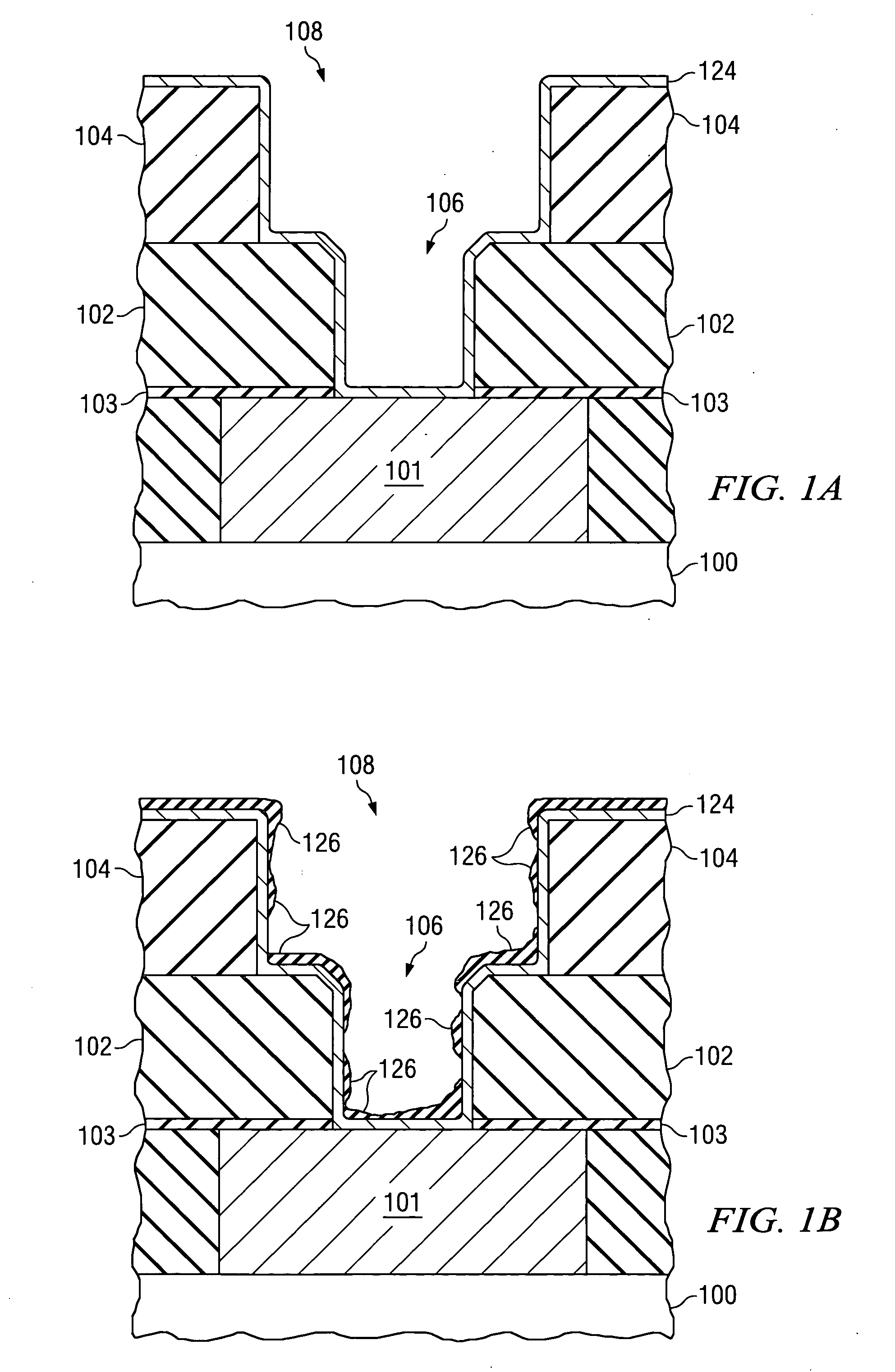
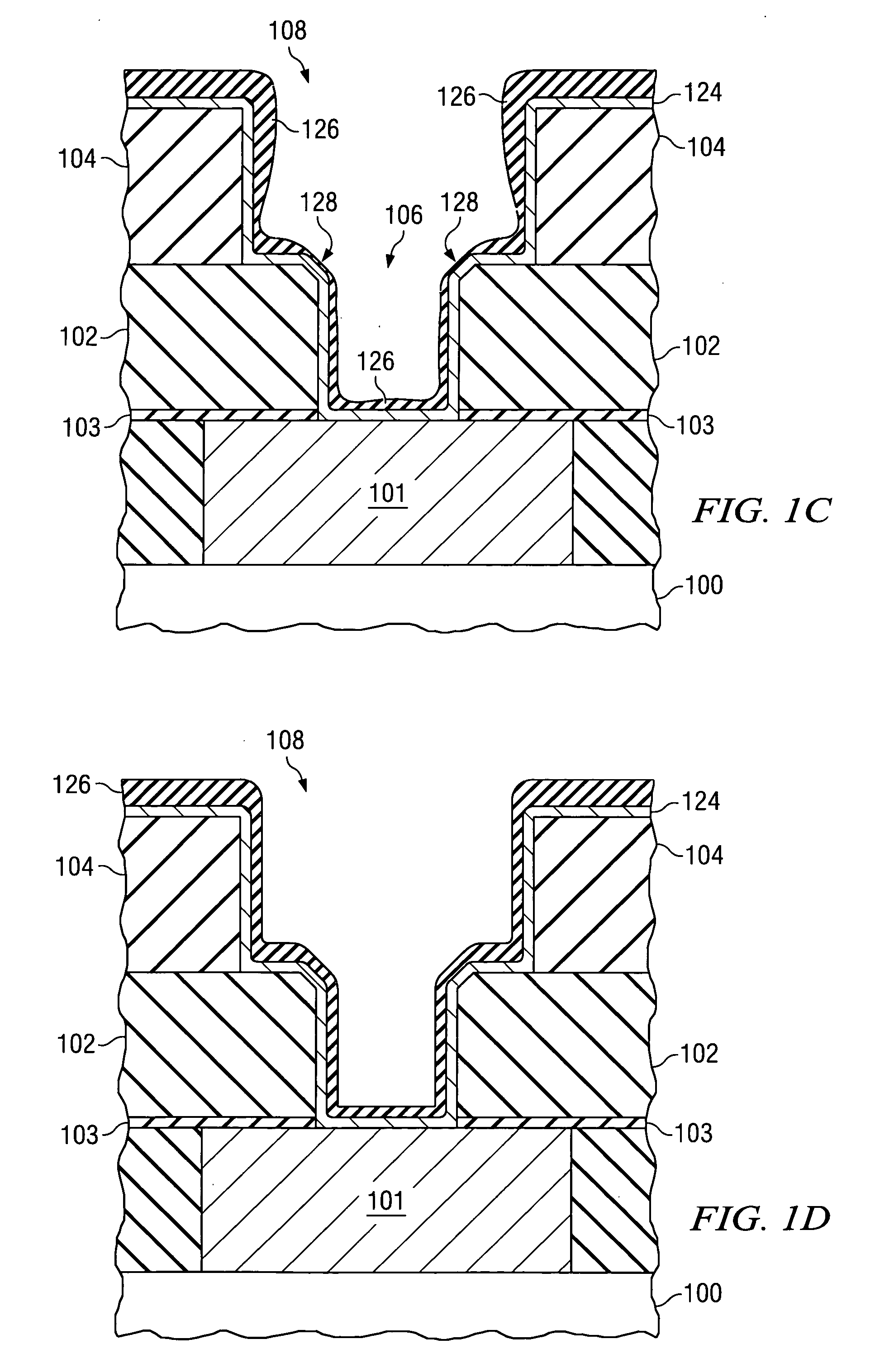
[0010] In a via-first dual damascene process, it is desirable to protect the via etch-stop layer during the trench etch. Accordingly, a temporary material may be applied to fill the via and protect the etch-stop layer at the bottom of the via during the trench etch. After trench pattern and etch, the temporary material is stripped from the via. BARC has been proposed as this temporary material. Alternatively, the invention uses a spin-on dielectric, such as HSQ (hydrogen silsesquioxane) or SOG (spin-on glass), as this temporary material.

[0011] A process for removing the spin-on dielectric after trench etch should minimally impact the via or trench structure. Wet strip processes can cause CD blow out (a widening of the trench or via) and have insufficient selectivities to adjacent materials. In addition, the wet strip may not result in complete removal of the spin-on dielectric.

[0012] In light of the problems with a wet strip of a spin-on dielectric, the invention uses a dry strip ...


PUM


Abstract

A spin-on dielectric (120) strip process. Instead of a wet strip, a dry strip process is used to remove the spin-on dielectric (120). In a via-first dual damascene method, a via (116) may be patterned and etched and the via (116) is filled with the spin-on dielectric (120). Then, the trench is patterned and etched while the spin-on dielectric (120) protects the bottom of the via (116). Finally, the spin-on dielectric (120) is removed using a dry strip process with a low ion energy plasma.

Description

FIELD OF THE INVENTION [0001] The invention is generally related to the field of forming integrated circuits and more specifically to an HSQ / SOG dry strip process that may be used in, for example, a dual damascene process flow for forming interconnect structures. BACKGROUND OF THE INVENTION [0002] As the density of semiconductor devices increases, the demands on interconnect layers for connecting the semiconductor devices to each other also increases. Therefore, there is a desire to switch from the traditional aluminum metal interconnects to copper interconnects and from traditional silicon-dioxide-based dielectrics to low-k dielectrics, such as organo-silicate glass (OSG). Semiconductor fabrication processes that work with copper interconnects and newer low-k dielectrics are still needed. As compared to the traditional subtractive plasma dry etching of aluminum, suitable copper etches for a semiconductor fabrication environment are not readily available. To overcome the copper etch...

Claims


Application Information

Patent Timeline
IPC IPC(8): H01L21/4763
CPCH01L21/76808H01L21/76807
Inventor ALI, ABBAS
Owner TEXAS INSTR INC
Why Eureka
Try Eureka