Ceramic manufactures

a technology of ceramics and manufacture methods, applied in the field of ceramic manufacture, can solve the problems of machining without harmful or contaminating substances, and achieve the effect of avoiding drawbacks

Active Publication Date: 2006-02-02
LOUIS A SERAFIN JR TRUST +1
View PDF53 Cites 51 Cited by
  • Summary
  • Abstract
  • Description
  • Claims
  • Application Information

AI Technical Summary

Benefits of technology

[0012] In general, the present invention provides, in one aspect, a method for making a ceramic body, which comprises providing an initial green body of ceramic; and machining the initial green body to provide a machined green ceramic body. In the method, in one embodiment, machining the initial green body can be carried out without embedding the initial green body in an embedding mass; in another embodiment, bisquing the initial green body can form a bisqued green body of ceramic, which can be infiltrated with an adjuvant, removed from any gross external adjuvant by which the bisqued green body was contacted for the infiltration, and machined as a removed, infiltrated, bisqued green body. For one instance, the machining may be conducted with the aid of a device that does not provide contact of the initial green body with an attachable substance, for example, machining wax. In such a case, and with the alternative, detailed and even highly detailed ceramic products can be generated without embedding in an embedding mass, and so, avoiding drawbacks associated with the same. The machined green ceramic body may be fired and / or further processed to provide a more finished ceramic body.

Problems solved by technology

Moreover, bothersome or contaminating substances are absent from the machining.

Method used


Image

  • Ceramic manufactures
  • Ceramic manufactures
  • Ceramic manufactures

Examples


example 1

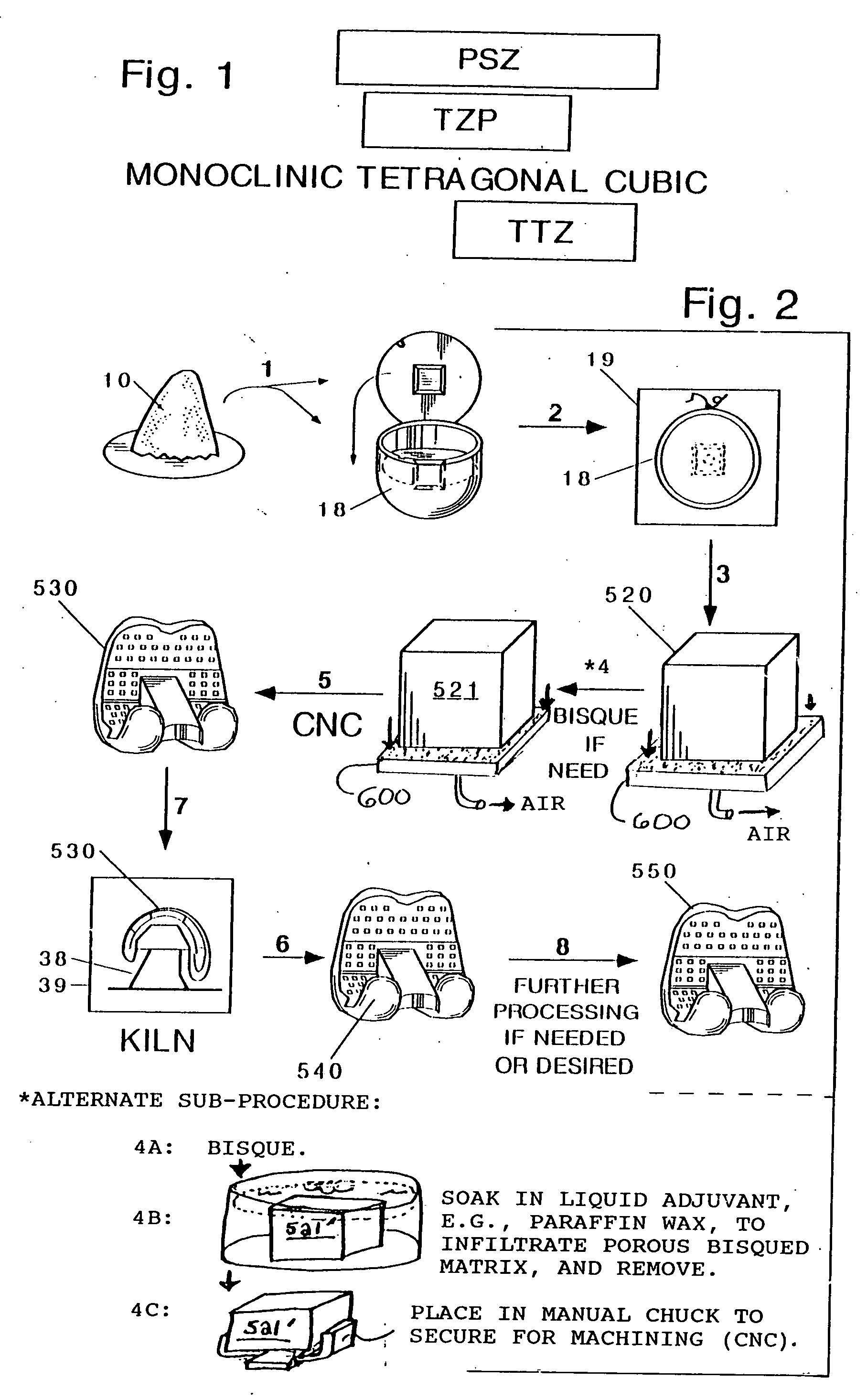
[0150] A finished body of a Mg-TTZ posterior stabilized femoral knee joint implant component was begun through CIP action on an about 3-percent magnesium oxide zirconia monoclinic 1-2 um micropowder with a binder, which was bisqued to provide a right angled 3½-inch×4-inch×4-inch block. Then CNC machining of the block provided a green machined body 121.95% of the size of the projected more finished ceramic, as a precursor to a posterior stabilized femoral knee component with standard sized condyles. The precursor was placed with its condyles up on fired Mg-TTZ kiln furniture in an oven, which was ramped at an about 1˜2-degree C. per minute rate from room temperature to a firing temperature of some 1725˜1775 degrees C. Firing was carried out for some 2˜3 hours. Then the temperature was reduced at an about 5-degree C. per minute rate to an about 1340-degree C. annealing temperature. Annealing was carried out for an about 2-hour time. The annealed ceramic was cooled to room temperature ...

example 2

[0156] A block for a machined green body of for a Y-TZP posterior stabilized femoral knee joint component was made through pressure upon a monoclinic nanopowder, without binder. The block can be CNC-machined to provide a machined green ceramic body, fired and annealed, and further processed with a 1200-degree C., 20,000-psi pressure HIP to provide a theoretically dense, posterior stabilized component.

example 3

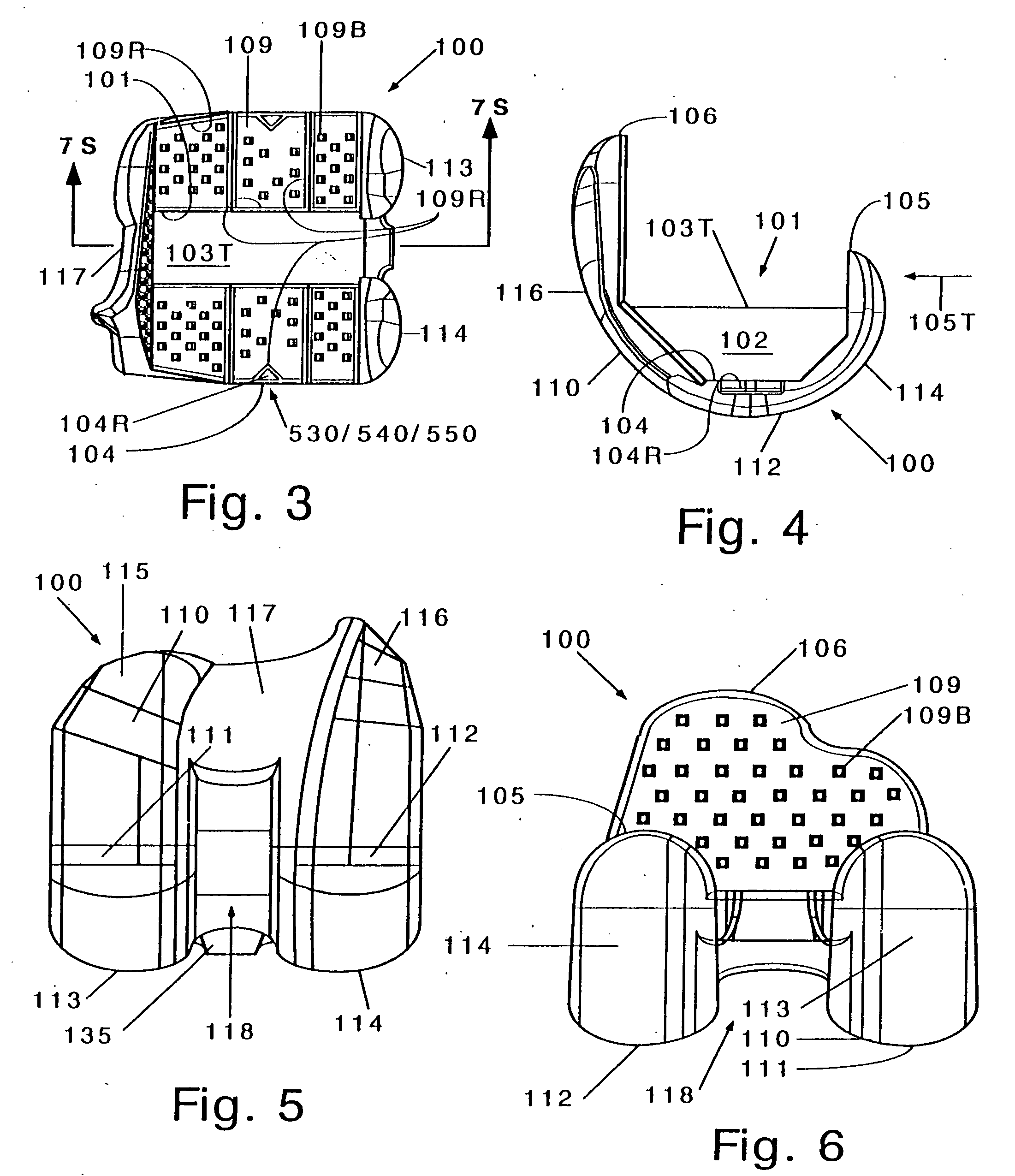
[0157] Mg-TTZ ceramic posterior stabilized knee femoral components 100 were made by the method of Example 1 but with infiltration of a bisqued green body with paraffin wax as adjuvant, removing the infiltrated body, and then machining the removed, infiltrated, bisqued green body. See, e.g., FIGS. 2-8.


PUM

PropertyMeasurementUnit
bevel anglesaaaaaaaaaa
shapeaaaaaaaaaa

Abstract

Ceramic bodies can be made by providing an initial green body of ceramic; and machining the initial green body to provide a machined green ceramic body. Embedding the initial green body in an embedding mass can be avoided. The initial green body can be bisqued, infiltrated an adjuvant such as machining wax, removing the infiltrated body, and machining it. Highly detailed ceramic products can be generated. The machined green ceramic body may be fired and/or further processed to provide a more finished ceramic body. Examples include a femoral component for a posterior stabilized knee implant, a component body for an artificial rotation device containing knee implant prosthesis a dental implant or bridge, an ice skating blade, and so forth. Zirconia ceramics are advantageously employed, for an example, Mg-TTZ.

Description

CROSS-REFERENCE CLAIMS OF PRIORITY [0001] This claims the benefits as a continuation-in-part of International Patent Application No. PCT / US2004 / 006908 filed on Mar. 5, 2004 A.D., which, as does the present matter, claims priority benefits of U.S. provisional patent application Nos. 60 / 452,704 filed on Mar. 7, 2003 A.D., and 60 / 463,922 filed on Apr. 18, 2003 A.D. In addition, this claims priority benefits of U.S. provisional patent application No. 60 / 677,240 filed on May 3, 2005 A.D. The same is claimed under 35 USC 119, 120, 363 and / or 365. The specifications of the above mentioned '908, '704, '922 and '240 applications are incorporated herein by reference in their entireties.FIELD AND PURVIEW OF THE INVENTION [0002] This invention concerns a method of manufacture of a ceramic body as well as the ceramic body itself. In a particular field, the ceramic body embraces a bodily implant, especially a load-bearing joint implant. For example, the implant may be a femoral knee component in ...

Claims


Application Information

Patent Timeline
Patent Type & Authority Applications(United States)
IPC IPC(8): A61F2/28
CPCA61C13/0003A61L27/10A61F2/38A61F2/4425A61F2/4684A61F2002/30133A61F2002/30433A61F2002/30443A61F2002/30492A61F2002/30604A61F2002/30616A61F2002/30714A61F2002/30736A61F2002/30841A61F2002/30843A61F2002/30892A61F2002/30991A61F2002/4205A61F2002/4207A61F2220/0025A61F2220/0041A61F2230/0015A61F2250/0089A61F2310/00239A61F2/3094A61F2002/3071A61F2310/00185A61F2310/00197A61F2310/00592A61F2/3859A61F2/3877A61F2002/30968A61F2002/3895B28B3/003B28B11/003B28B11/08B28B11/24
Inventor SERAFIN, LOUIS A. JR.JERRY, GERALD J. JR.BURLINGAME, NICHOLAS H.
Owner LOUIS A SERAFIN JR TRUST
Why Eureka
Try Eureka