

Lamination cooling system formation method
a technology of lamination cooling and stacking, which is applied in the direction of magnets, magnetic circuit shapes/forms/construction, magnetic bodies, etc., can solve the problems of increasing increasing the thermal impedance between, and reducing the continuous power rating of the motor, so as to reduce the cost of manufacturing a liquid cooled housing. , the effect of reducing the cost of manufacturing
- Summary
- Abstract
- Description
- Claims
- Application Information
AI Technical Summary
Benefits of technology
Problems solved by technology
Method used
Image

Examples
first embodiment
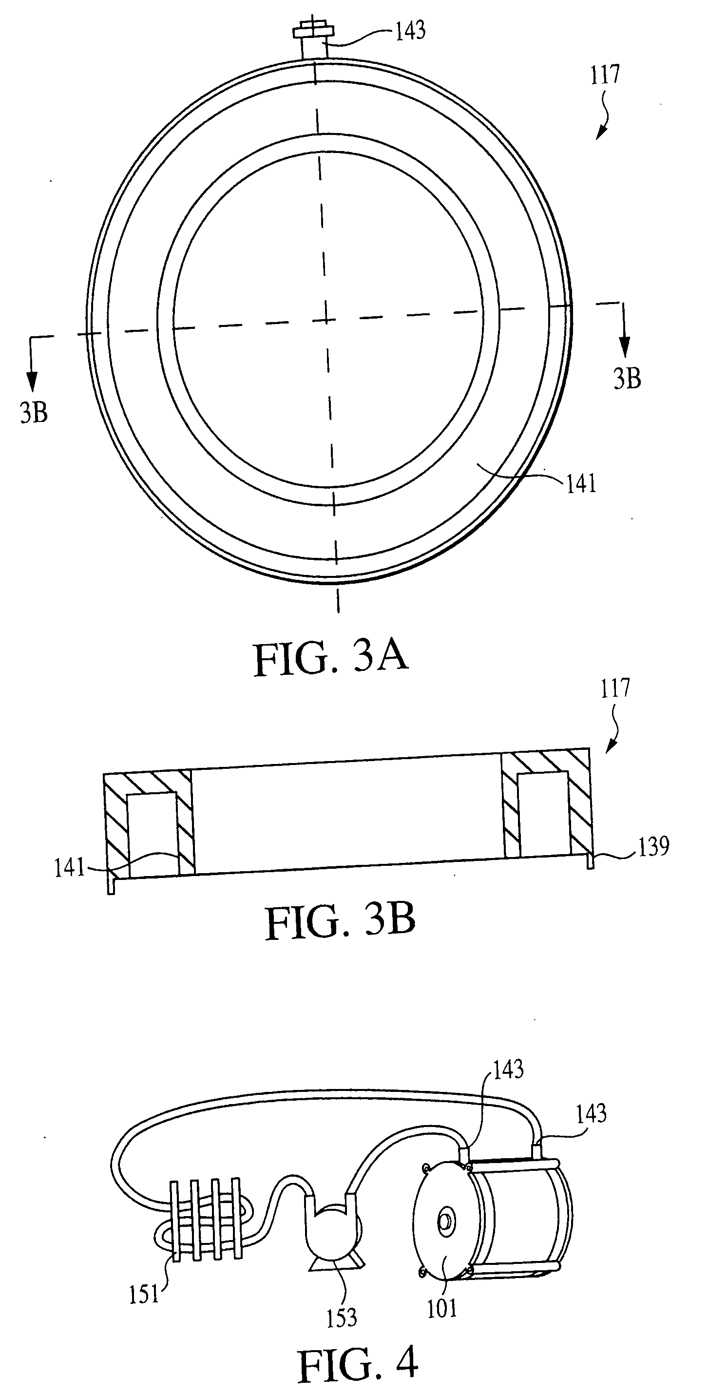
[0058] With reference to FIGS. 5A-5C, a first variation of stator housing of the type described in the first embodiment can be configured for bidirectional flow. Rather than using first and second manifold members each having a cooling-fluid port and a single circumferential manifold cavity, the manifold members are configured to direct cooling fluid bidirectionally through a lamination stack 215. More particularly a first manifold member 211 is configured with a first cooling-fluid port 261, a second cooling-fluid port 263, a first semi-circumferential manifold cavity 265 and a second semi-circumferential manifold cavity 267. The first cooling-fluid port 261 is in direct fluid communication with the first semi-circumferential manifold cavity 265, and the second cooling-fluid port 263 is in direct fluid communication with the second semi-circumferential cavity 267. A second manifold member 217 is configured with a single circumferential manifold cavity 271, and no cooling-fluid port...
second embodiment
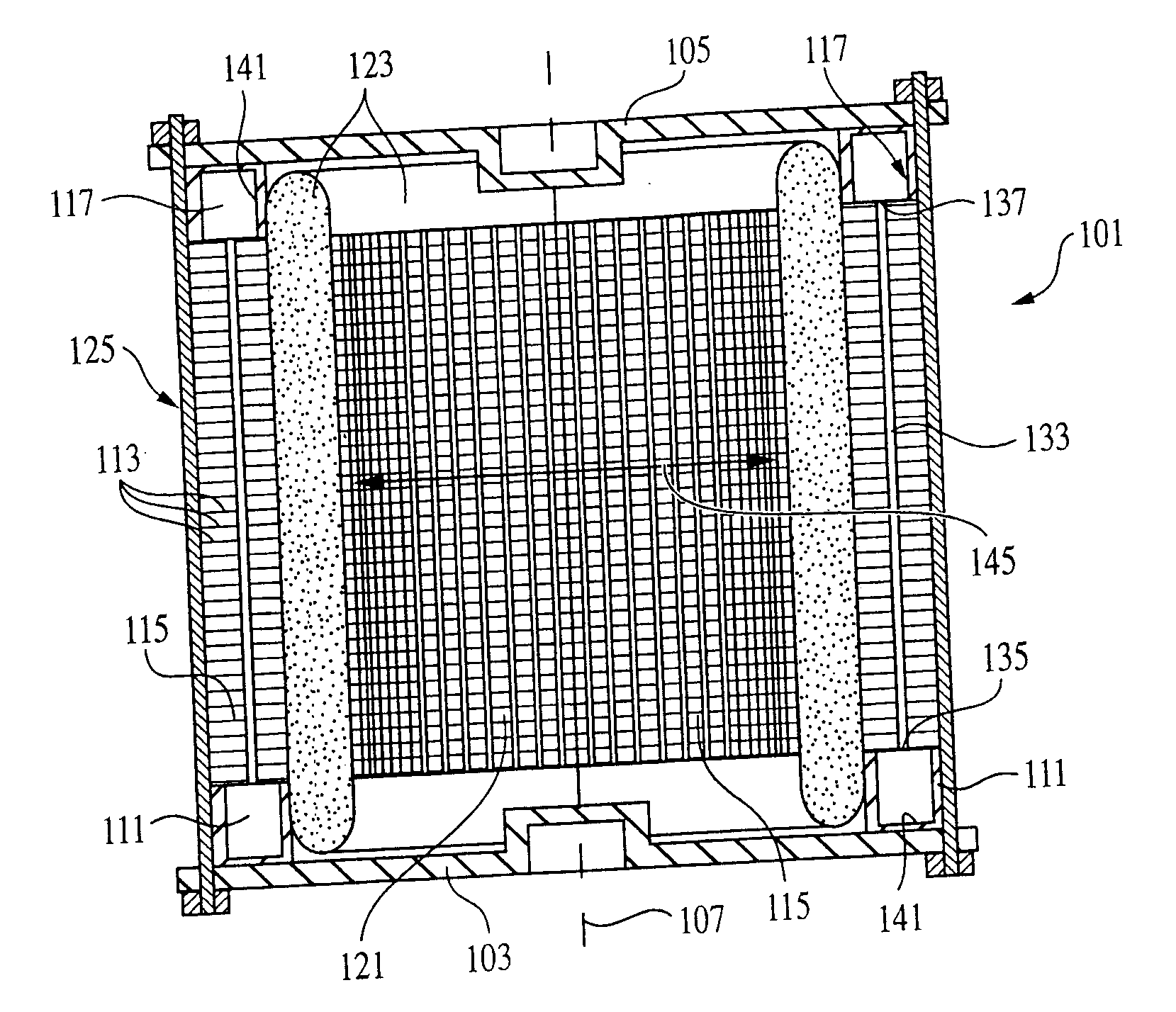
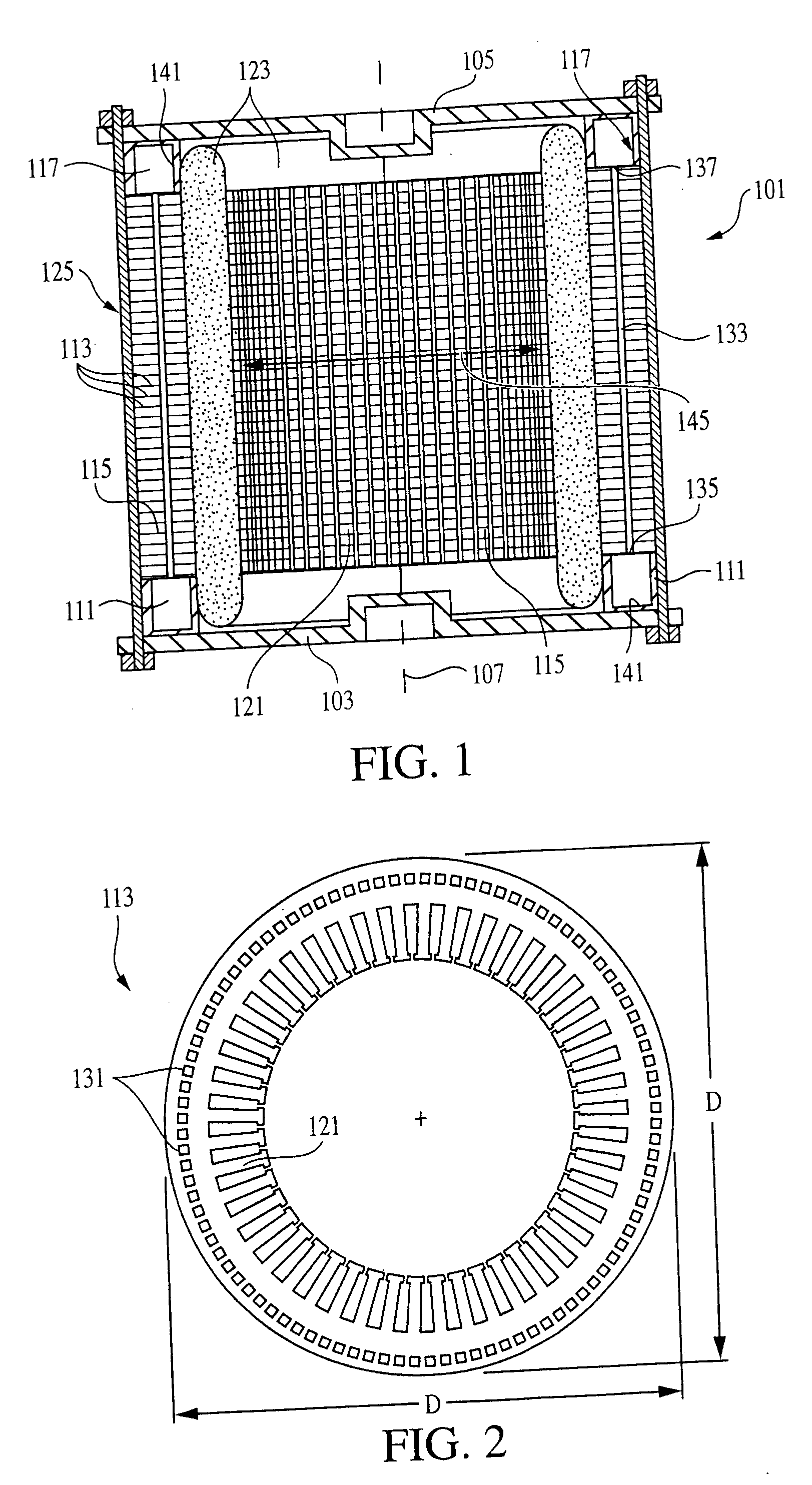
[0081] Manifold member designs for the second embodiment resemble those of the motor embodiment described above, but are rectangular rather than round. Similar to the various embodiment variations of the motor, each manifold member 505, 507 of the inductor / transformer embodiment includes one or more cooling-fluid ports 519, and forms one or more cavities that are used as manifolds to distribute and / or receive cooling fluid to / from the passageways 517 within the core structure 501. As with the manifold members for the motor application, sealing between the manifold members and the lamination stack faces can be achieved by either conventional gasket techniques or by conventional O-ring techniques.
[0082] Because it is desirable to have cooling provided to the center prong 509 of the E-shaped element, and because the windings 503 prevent direct access between the manifold members 505, 507 and center-prong passages 521 that pass through the center prong, the core 501 includes nonlinear, ...
PUM
| Property | Measurement | Unit |
|---|---|---|
| heat transfer | aaaaa | aaaaa |
| inner diameter | aaaaa | aaaaa |
| outer diameter | aaaaa | aaaaa |
Abstract
Description
Claims
Application Information