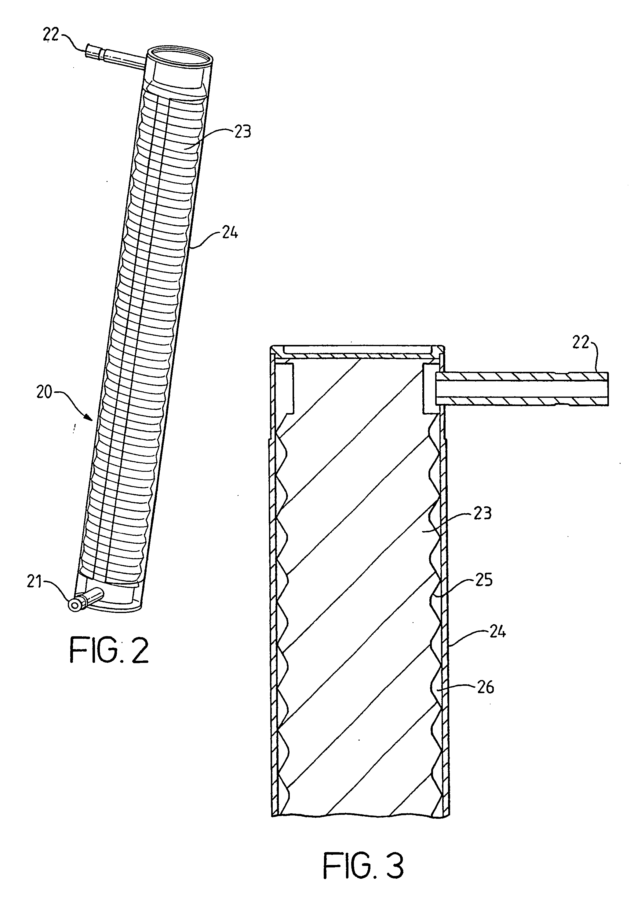
[0018] The heating module according to the invention, with resistors on a tube, comprises further a cylindrical insert, which is disposed inside the hollow tube, along its entire length and substantially along its
axis of symmetry. The fact that an insert is present enhances
heat transfer from the tube surface to the liquid by increasing the water speed which increases the transfer coefficient. The best speed is when a turbulent flow is reached. This allows a good transfer of energy and a quick heating of the water. The insert is made of plastic,
metal or
ceramic material, which is
food grade. The insert is preferably in a low thermal capacity and
conductivity material such as plastic and especially teflon (
tetra-fluoro-
ethylene), but can also be in another
food grade material. The ratio of the
diameter of the hollow tube to the
diameter of the insert is comprised between 1 and 5. It is possible to have either a fixed insert or an insert, which can be rotated along its
axis of symmetry. In the case of a rotating insert, said insert is connected with a rotating wheel of a flowmeter disposed at the lower part of the insert and so it can be powered by the flowing cold water, which flows in a tangent angle on to the flowmeter
propeller. The rotatable cylindrical insert comprises a
metal wire brush. These
metal brush bundles are integrated through the insert in a
longitudinal plane (on one side only or two symmetric sides of the insert) or on a spiral way, for example 1 or 2 spirals. They are built only in the insert part inside the hollow tube. The
brush should be of proper mechanical tensile and strength so that it can descale the inner tube surface. Both the
brush bundle ends should be slightly contacted with the inside surface of the tube at 90°. The whole bundles should be designed to push water upwards when it is powered to rotate by the flowmeter
propeller.
[0019] The insert can also be a hollow object, which will introduce a reversed flow of part of the hot water to mix with the cold water and so to enhance water mixing when the water is heated.
[0032] One of the
advantage of the process of the invention is that, the machine is always immediately ready to provide hot water at the required temperature or steam without
energy consumption during the stand-by phases. For example, there is no more
waiting time, when the
consumer pushes the “on” position of the machine and the moment when the machine is ready to prepare a coffee. When the
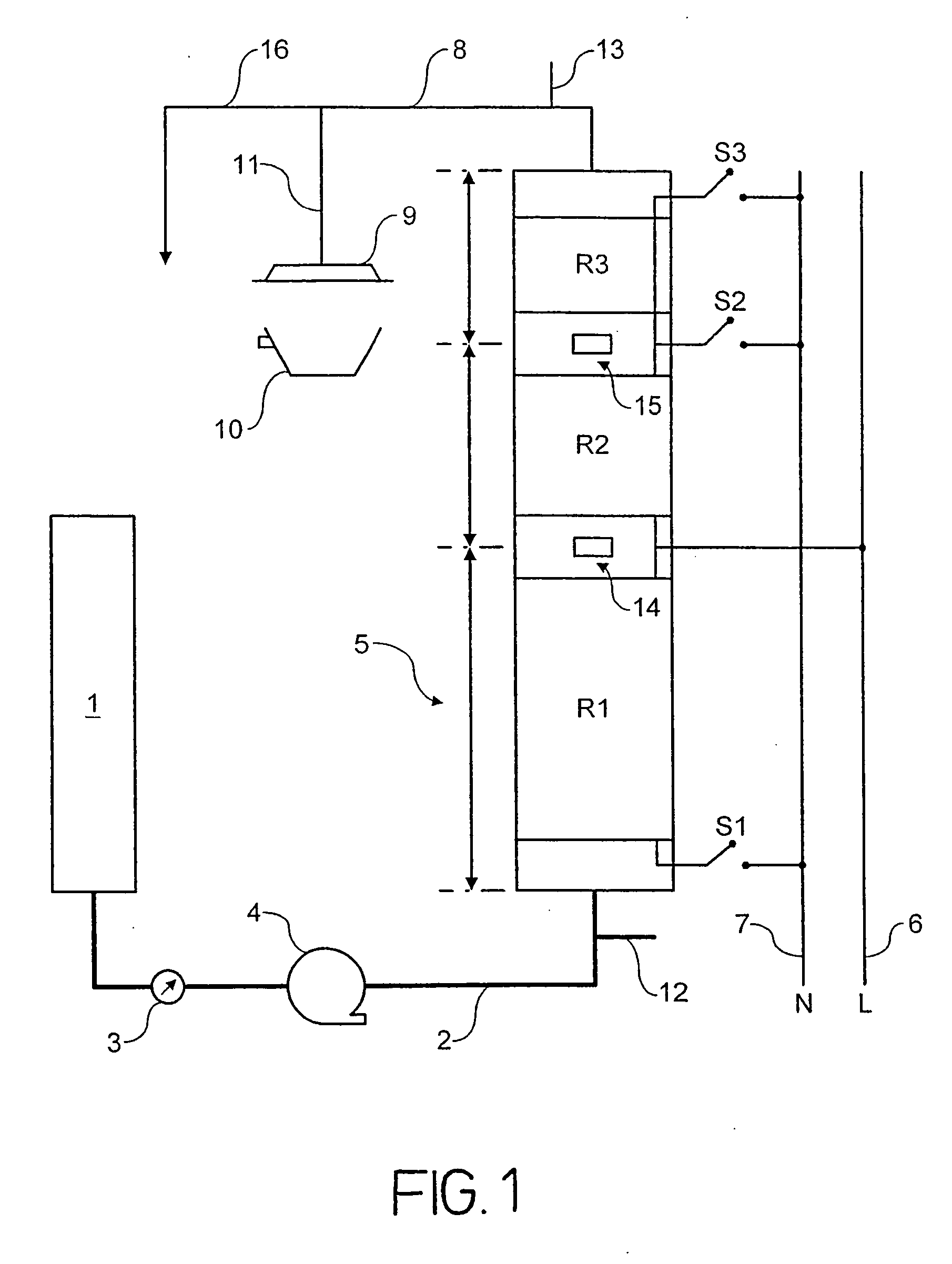
consumer decides to prepare a coffee, the pump moves the water to flow in the tube at the level of the first resistor, the pump stops and the first resistor heats the water at a temperature around 72° C. When the necessary energy to heat the amount of water under the first resistor has been delivered, the pump starts again and the water fills the tube at the level of the second resistor. Then, this second resistor heats the cold water coming from the first resistor at 72° C. to around 80° C. and in the same time, the first resistor heats the new cold water coming at ambient temperature to 72° C. The pump starts again and fills the tube to the level of the third resistor, then the second and third resistors are electrically linked in serial to heat the water to 86° C. and the first resistor heats the new cold water from ambient temperature to 72° C. Then, the pump starts again and the water is heated continuously (without any pump stop) to extract the coffee in the cup. Depending on coffee, the procedure takes around 20 to 30 seconds. For the next coffee, the same procedure is repeated.
[0033] Another solution consists to fill at the level of the last resistor with a reduced flow-rate (for example by varying the frequency of the pump) and to start at full flow-rate as soon as the last resistor is reached.

