Apparatus and method for measuring the temperature of substrates

a technology of substrates and apparatuses, applied in the direction of optical radiation measurement, muffle furnaces, furnaces, etc., can solve the problems of temperature drift, limited heat transfer speed of substrates, and limited cooling rate of substrates

Inactive Publication Date: 2006-02-09
MATTSON TECHNOLOGY +1
View PDF11 Cites 16 Cited by
  • Summary
  • Abstract
  • Description
  • Claims
  • Application Information

AI Technical Summary

Benefits of technology

[0036] In accordance with the second embodiment of the invention, it is advantageous that changes in intensity (both in terms of space and in terms of time) of the heating apparatus and / or its virtual images (for instance due to wafer vibrations) do not affect the temperature measurement of the object. This is because the measured intensities experience the same relative changes from the heating apparatus as from its virtual images, and these are therefore synchronously detected both by the first radiation detector and by the measurement apparatus. This means that, for instance by finding ratios of intensity values, the effects of changes in intensity (both in terms of space and in terms of time) can be compensated in the temperature measurement. It is advantageous when the intensity-dependent function, which also includes an intensity-independent proportionality factor, is approximately equal for each heating element.
[0040] A plurality of radiation detectors for measuring the radiation coming from the object is particularly advantageous when the object is rotatable by means of a rotation apparatus. Then surface regions of the object can be detected at different radial distances due to the arrangement of the second radiation detectors relative to the axis of rotation of the rotation apparatus, which makes it possible to acquire a radial temperature profile. It is this site-selective temperature determination of the object that makes it possible to adjust a radial temperature profile that is regulatable in wide limits across the wafers by controlling the heating elements of the heating apparatus, for instance of rod-shaped lamps, in particular halogen or arc lamps. It is advantageous when the electromagnetic radiation of each heating element is individually adjustable via a control apparatus.
[0042] It is furthermore advantageous when the fields of vision of the radiation detectors are adapted to the symmetry of the heating elements. Thus, for instance when rod-shaped heating elements are used, a rectangular field of vision, for instance, can be defined by suitable means such as restrictors and / or an optical imaging system comprising lenses, Fressnel lenses and / or zone plates. If the heating apparatus comprises rod-shaped heating elements arranged parallel to one another, the fields of vision of the radiation detectors are advantageously largely determined by cylindrical lenses arranged coaxially to the heating elements. This has the advantage that a field of vision opens perpendicular to the cylindrical lens axis, wherein the reflectivity of the object, which is integrated over a large angle, can be determined. Furthermore the determination of intensity using such fields of vision is not sensitive to vibrations in the object (wafer). In general the restriction of the fields of vision can be arranged such that, assuming an object that is reflective for the electromagnetic radiation of the heating apparatus, a minor displacement of a field of vision and the heating element relative to one another does not significantly affect the intensity measured by the radiation detectors. How this design is arrived at depends in general on the geometry of the heating apparatus and / or heating elements.

Problems solved by technology

In the one-sided heating systems it is disadvantageous that the speed at which the substrate is heated is limited due to the one-sided heating, whereby in general additional undesired temperature gradients caused by structures on the substrate surface occur within the substrate, in particular when the structures are formed or are present on the side of the substrate that faces the heat source.
This highly reflective chamber limits the rate at which the substrate cools, which is disadvantageous in many processes.
An additional disadvantage is that deposits such as condensation can occur when chamber walls are highly reflective, which changes the reflectivity of the walls, causing a temperature drift.
However, in contrast to the one-sided heating system, when there is two-sided heating the radiation measured by the wafer pyrometer is overlaid with an interfering radiation coming from the lamps due to the reflective properties of the substrate.
In particular this skews the amount of lamp radiation by reflection, which results in an error in the temperature measurement.
Not only does the option for the control result in numerous advantages in terms of temperature homogeneity across the wafer surface and flexibility with regard to the heating process, it also results in disadvantages for determining the temperature of the substrate or wafer, in particular when conventional wafer and lamp pyrometers are used.
Thus, as described above, elements of the pyrometer, or more generally of the temperature sensors, that restrict the field of vision can have a negative effect on temperature measuring accuracy, especially when the intensities of the wafer and lamp pyrometers are compared for measuring the temperature in order, for instance, to correct the effect of the reflection of the lamp radiation on the substrate surface.
For example, the vibrations of the substrate cited above, for instance, but also possible changes in intensity of individual heating elements in the heating apparatus, can interfere with the measurement result, in particular when the heating apparatus does not radiate uniformly in space.

Method used


Image

  • Apparatus and method for measuring the temperature of substrates
  • Apparatus and method for measuring the temperature of substrates
  • Apparatus and method for measuring the temperature of substrates

Examples


Embodiment Construction

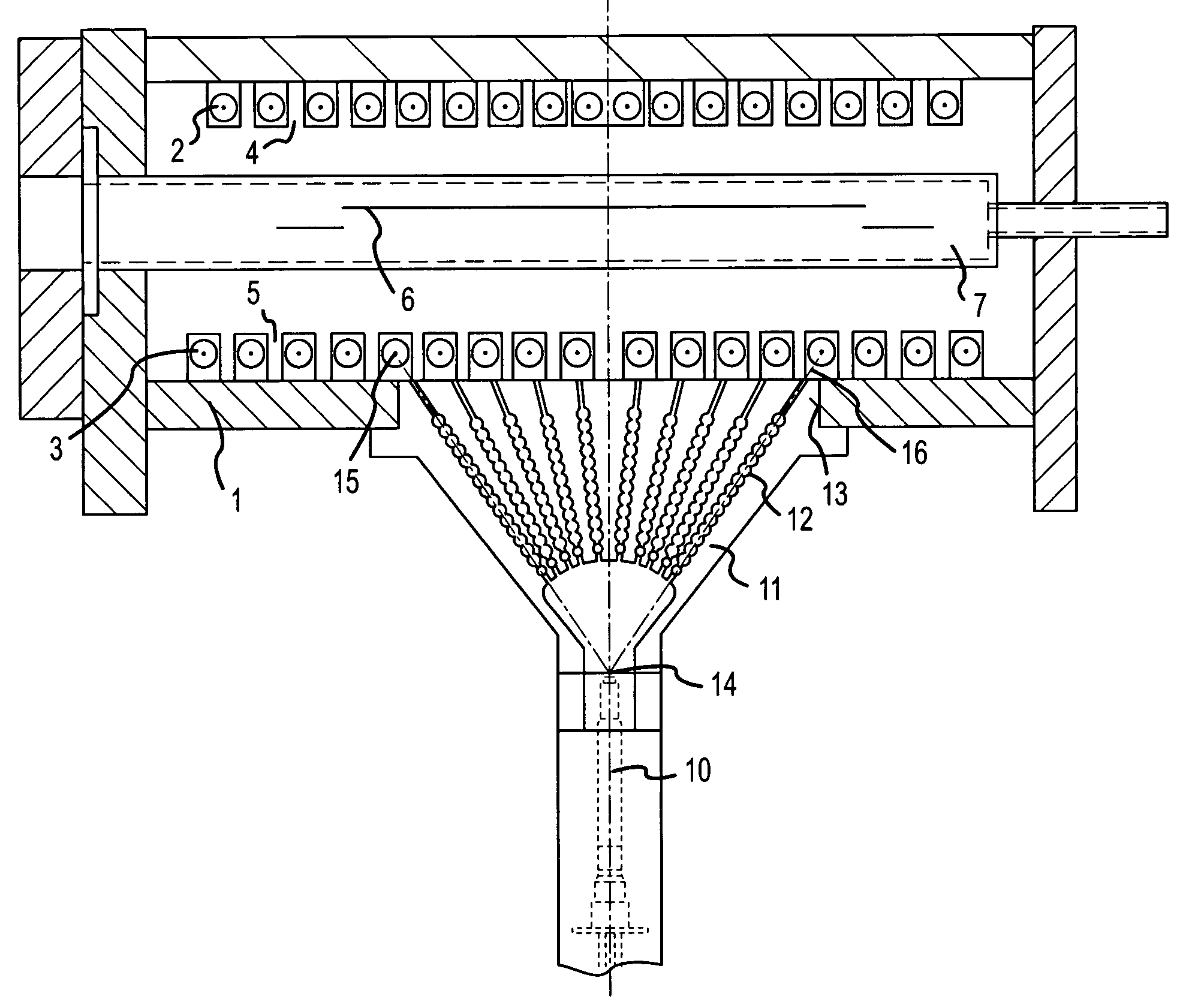
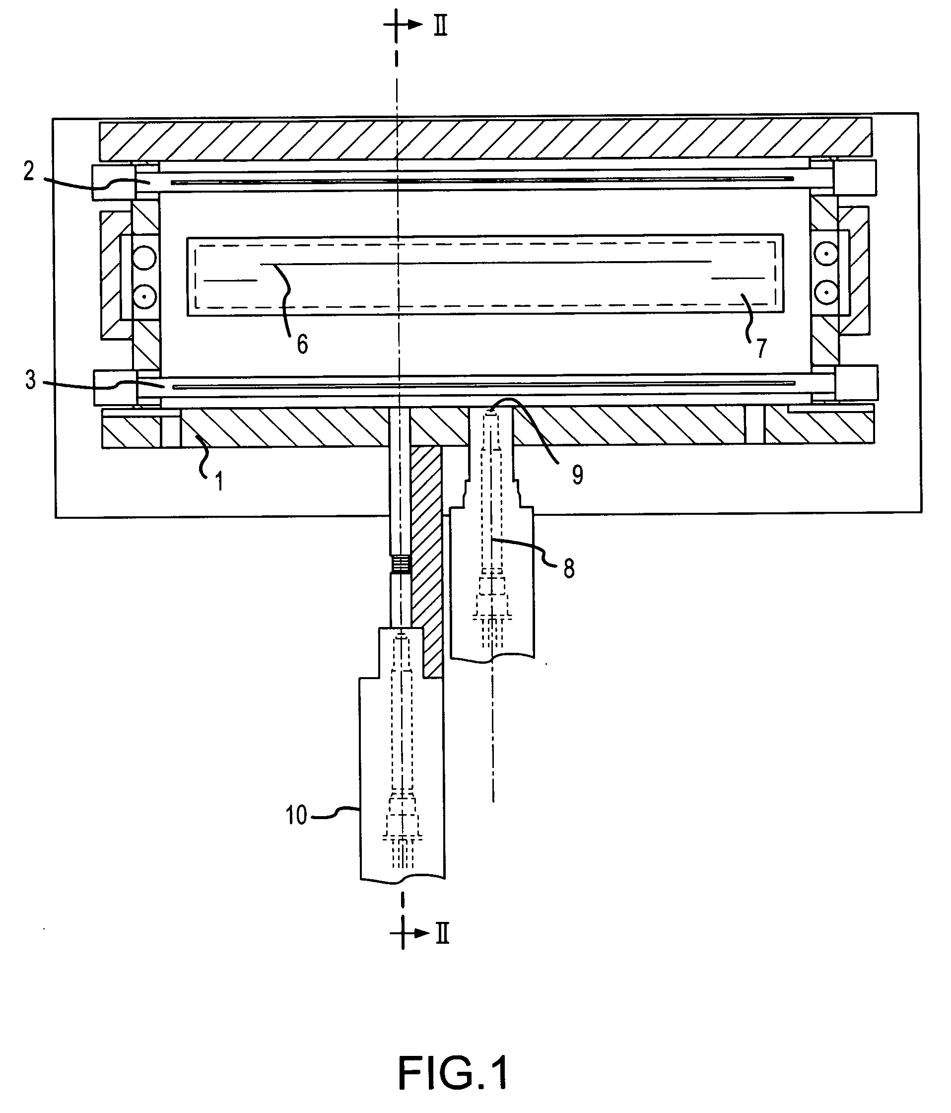
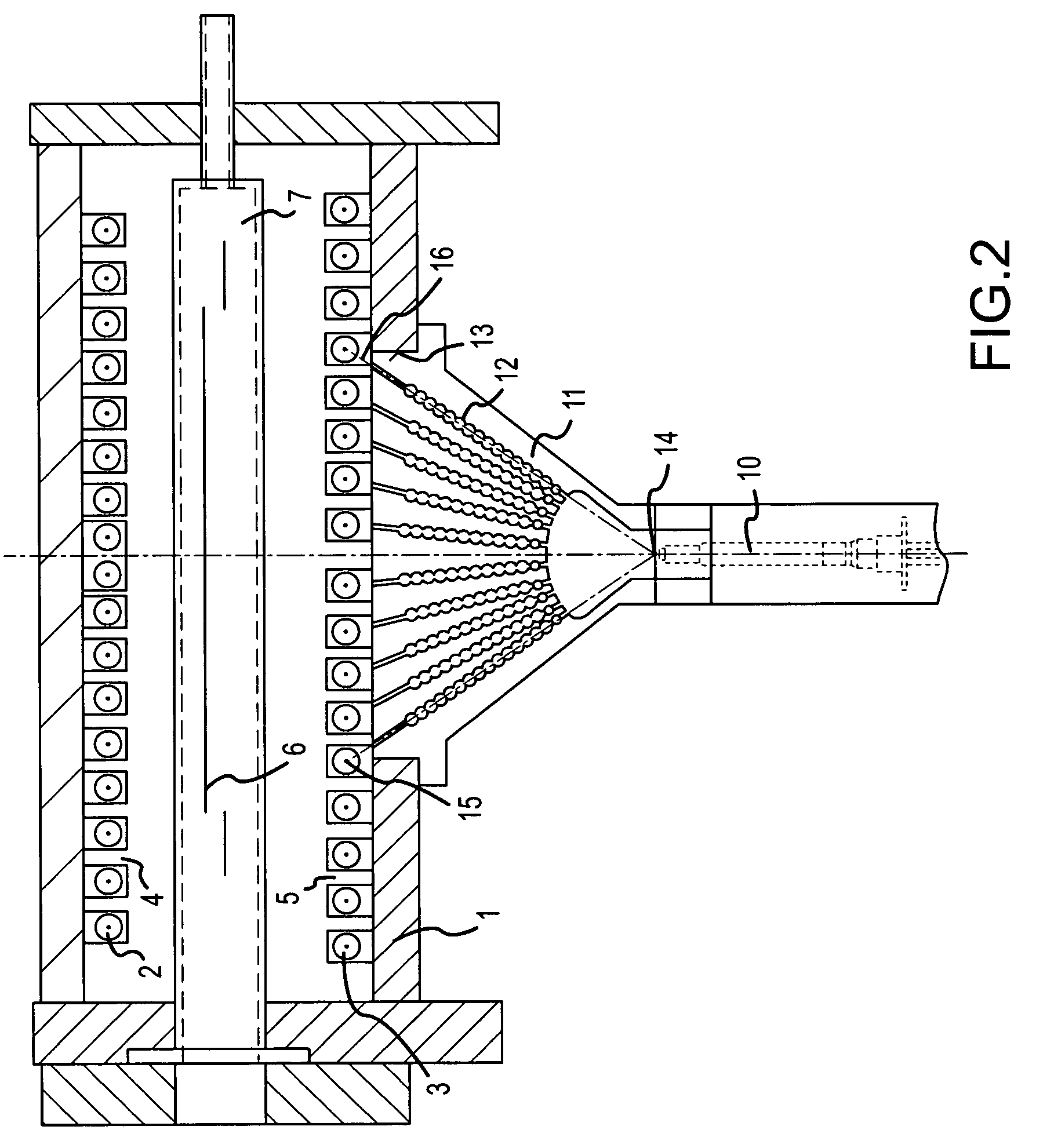
[0056] The rapid heating oven illustrated in FIGS. 1 and 2 has a housing 1, to the upper and lower interior wall of which are attached banks of lamps 4, 5 comprising a plurality of individual lamps or individual lamp tubes 2, 3, which heat a semiconductor wafer 6 that is arranged in a reaction chamber 7 between the banks of lamps 4, 5 in the housing 1.

[0057] Advantageously the reaction chamber 7 essentially comprises a material that is largely transparent for the lamp radiation, which material is also transparent with regard to the measuring wavelengths or measuring wavelength spectra of the pyrometers or the radiation detectors used. Using silica glass and / or sapphire, which have an absorption coefficient of approximately 0.1 1 / cm to 0.001 1 / cm determined via the lamp spectra, reaction chambers that are suitable for rapid heating systems can be built in which the thickness of the reaction chamber wall can be between 1 mm and several centimeters. The material can be selected in ter...


PUM

PropertyMeasurementUnit
thicknessaaaaaaaaaa
thicknessaaaaaaaaaa
reflectivityaaaaaaaaaa

Abstract

An apparatus for measuring an object temperature of an object, and including at least one heating apparatus having at least one heating element for heating an object via electromagnetic radiation. Also included is at least one first radiation detector that detects radiation coming from the object within a first field of vision, and, for determining correction parameters, a measuring device that detects the electromagnetic radiation that reaches the first field of vision from the at least one heating element up to a proportionality factor or a known intensity-dependent function.

Description

RELATED APPLICATIONS [0001] This application is a continuation of Ser. No. 09 / 913,269 filed Aug. 10, 2001 with a 371 date of Nov. 16, 2001, and now allowed.BACKGROUND OF THE INVENTION [0002] The present invention relates to a method and an apparatus for measuring the temperature of substrates, in particular semiconductor substrates or wafers, with at least one radiation detector for measuring the radiation emitted by the substrate, and an element that restricts the field of vision of the radiation detector and that is arranged between the substrate and the radiation detector. The invention furthermore relates to an apparatus for measuring an object temperature of an object, with at least one heating apparatus including at least one heating element for heating the object by means of electromagnetic radiation, with at least one first radiation detector that detects the radiation coming from the object within a first field of vision. [0003] The invention described in greater detail in ...

Claims


Application Information

Patent Timeline
Patent Type & Authority Applications(United States)
IPC IPC(8): F27B5/14G01J5/00G01J5/08
CPCG01J5/0003G01J5/0007G01J5/06G01J2005/0048G01J5/0806G01J5/0831G01J5/0846G01J5/08G01J5/80
Inventor HAUF, MARKUS
Owner MATTSON TECHNOLOGY
Why Eureka
Try Eureka