Optical pickup device, optical disk apparatus, and light-receiving unit

a pickup device and optical disk technology, applied in the direction of optical recording heads, instruments, data recording, etc., to achieve the effect of optimal optical system and reduction of spherical aberration in short wavelength ligh

Inactive Publication Date: 2006-02-09
PANASONIC CORP
View PDF24 Cites 65 Cited by
  • Summary
  • Abstract
  • Description
  • Claims
  • Application Information

AI Technical Summary

Benefits of technology

[0010] An object of the present invention is to provide an optical pickup device and an optical disk, which are capable of accomplishing improved optical configuration in each wavelength and implementing miniaturization.
[0012] According to the above structure of the invention, since the lens can be disposed at a predetermined position in each wavelength, the spherical aberration in the short wavelength light can be reduced, and an optimal optical system can be implemented in the long wavelength light. Also, the movable lens is provided on almost the same optical path along which the short wavelength light and the long wavelength light are to be guided, so that a minimum number of components can be used to obtain the effect, thereby allowing the device to be small-sized.

Problems solved by technology

However, in an optical pickup which records and reproduces information on an optical disk with short wavelength light and long wavelength light, the patent documents do not disclose any configuration in which the spherical aberration in the short wavelength light is corrected, and an optimal optical system in the long wavelength light is accomplished, thereby making the apparatus as small as possible.

Method used


Image

  • Optical pickup device, optical disk apparatus, and light-receiving unit
  • Optical pickup device, optical disk apparatus, and light-receiving unit
  • Optical pickup device, optical disk apparatus, and light-receiving unit

Examples


Embodiment Construction

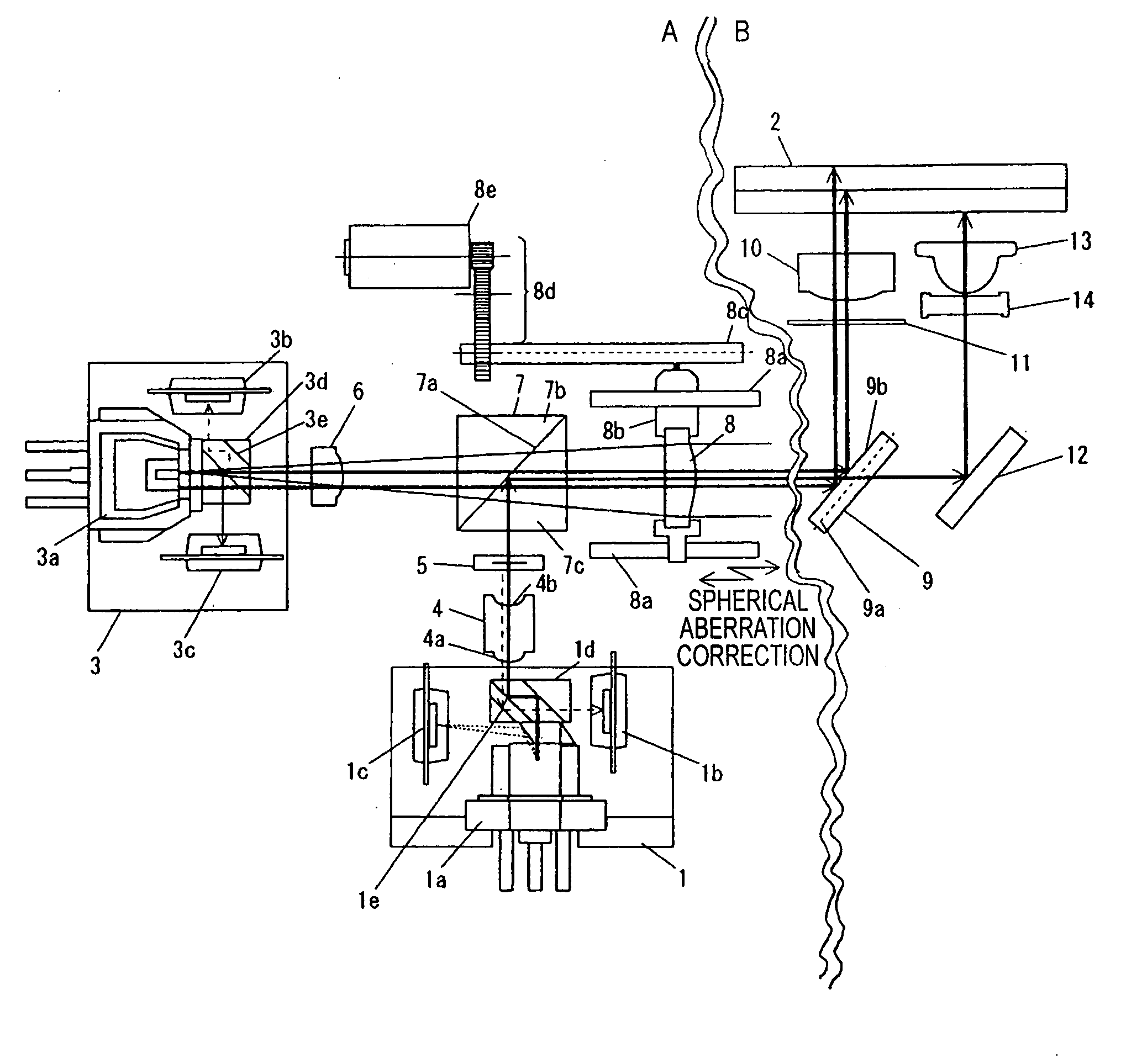
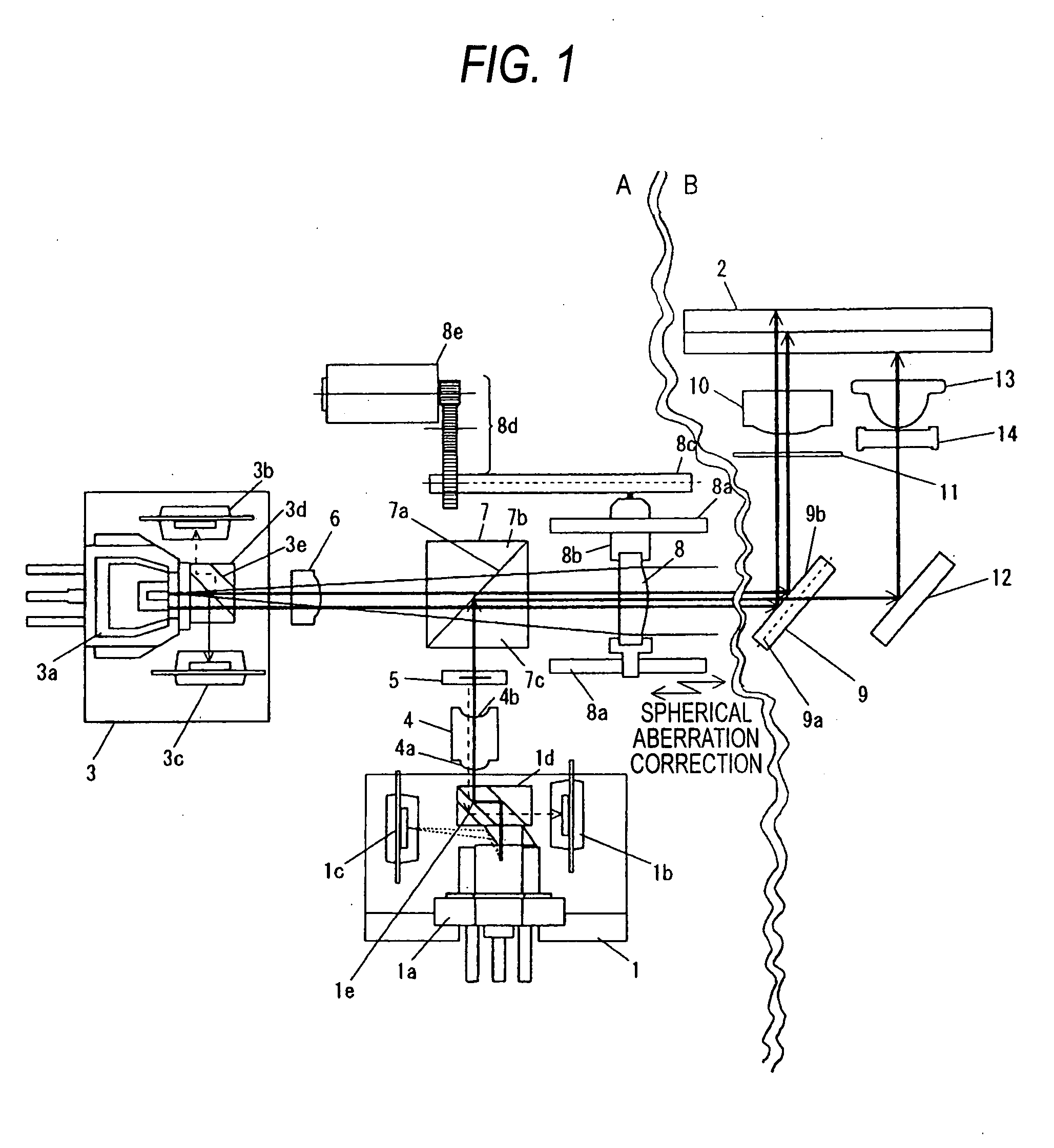
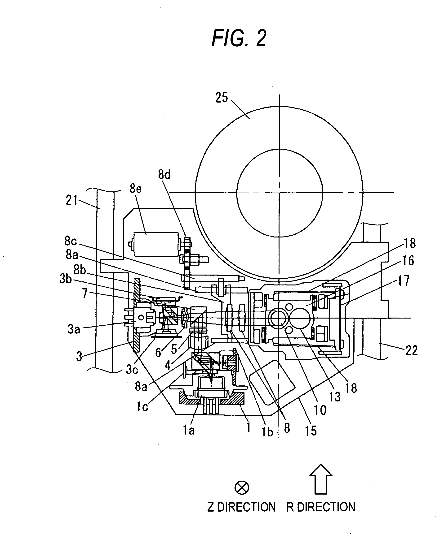
[0079]FIG. 1 is a schematic view illustrating a structure of an optical pickup device in accordance with an embodiment of the present invention. In addition, referring to FIG. 1, the portion A of double undulating lines ranging from a short wavelength optical unit 1 or a long wavelength optical unit 2 to a collimator lens 8, is a schematic view when the optical pickup device is seen from a Z direction (top of the paper) in FIG. 2, and the portion B of the double undulating lines ranging from a starting mirror 9 to an optical disk 2 is a schematic view when the optical pickup device is seen from an R direction in FIG. 2.

[0080] Referring to FIG. 1, reference numeral 1 denotes a short wavelength optical unit which emits short wavelength laser light. The light emitted from the short wavelength optical unit 1 has a wavelength of about 400 nm to 415 nm. In the present embodiment, the short wavelength optical unit is adapted to emit light of about 405 nm. In addition, the light of the abo...


PUM

PropertyMeasurementUnit
wavelengthaaaaaaaaaa

Abstract

An optical pickup device, comprises a first light source emitting light with a short wavelength; a second light source emitting s light with a wavelength longer than that of the first light source; an optical member guiding the light from the first light source and the light from the second light source on almost the same optical path; a focusing member focusing the light from the optical member; a movable lens provided between the optical member and the focusing lens; and a drive member driving the movable lens, wherein a position of the lens when at least one of recording and reproducing of information is carried out on a medium using the light from the first light source is made different from a position of the lens when at least one of the recording and reproducing of information is carried out on the medium using the light from the second light source.

Description

BACKGROUND OF THE INVENTION [0001] 1. Field of the Invention [0002] The present invention relates to an optical disk apparatus which can be mounted on electronic equipment such as stationary personal computers or portable electronic equipment such as notebook personal computers, and an optical pickup device mounted on the optical disk apparatus. [0003] 2. Description of the Related Art [0004] In optical disk apparatuses, recently, it has been required to perform recording and reproducing on CDs or DVDs with an infrared laser or a red color laser, and it has also been required to perform at least one of recording and reproducing of information on optical disks corresponds to a short wavelength laser such as a blue color laser. [0005] Conventional Examples are disclosed in JP-A No. 2003-771631, JP-A No. 2002-245660, JP-A No. 2004-103189, JP-A No. 2004-152426, JP-A No. 2004-158102, JP-A No. 2003-77167, JP-A No. 2003-59080, JP-A No. 2000-131603, JP-A No. 2003-85806, JP-A No. 2004-206763...

Claims


Application Information

Patent Timeline
Patent Type & Authority Applications(United States)
IPC IPC(8): G11B7/00
CPCG11B7/0932G11B7/0933G11B7/0935G11B7/1205G11B7/1275G11B2007/13727G11B7/1369G11B7/1376G11B7/13925G11B7/1398G11B2007/0006G11B7/1359G11B7/123
Inventor MORI, TAIICHIHORINOUCHI, SHOGOYOSHINAKA, HIDEKIHARUGUCHI, TAKASHIOHYAMA, HIDEKIISHIBASHI, SHINASO, JUNYAYOSHIMOTO, TSUYOSHIMAEHARA, YOUICHI
Owner PANASONIC CORP
Why Eureka
Try Eureka