Methods and devices for improving breathing in patients with pulmonary disease

Inactive Publication Date: 2006-02-16
GYRUS ACMI INC (D B A OLYMPUS SURGICAL TECH AMERICA)
View PDF58 Cites 123 Cited by
  • Summary
  • Abstract
  • Description
  • Claims
  • Application Information

AI Technical Summary

Benefits of technology

[0012] According to the present invention, there is a potentially significant benefit for a patient who undergoes a simple procedure that creates an obstruction to expiratory airflow within the airways. There are several possible means of achieving the requisite expiratory obstruction. A device capable of delivering energy (radiofrequency, ultrasound, microwave, laser, cryo) could be used to create a localized scarring or area or stenosis in the appropriate loc

Problems solved by technology

Typically, patients with COPD have extensive smoking histories; smoking is the major risk factor for development of COPD.
Medications including bronchodilators (including beta-agonists, anti-cholinergics, and theophylline) and anti-inflammatories are routinely prescribed but are by no means curative.
Surgical options are limited and include lung volume reduction surgery and lung transplantation.
Both of these surgical optio

Method used


Image

  • Methods and devices for improving breathing in patients with pulmonary disease
  • Methods and devices for improving breathing in patients with pulmonary disease
  • Methods and devices for improving breathing in patients with pulmonary disease

Examples


first embodiment

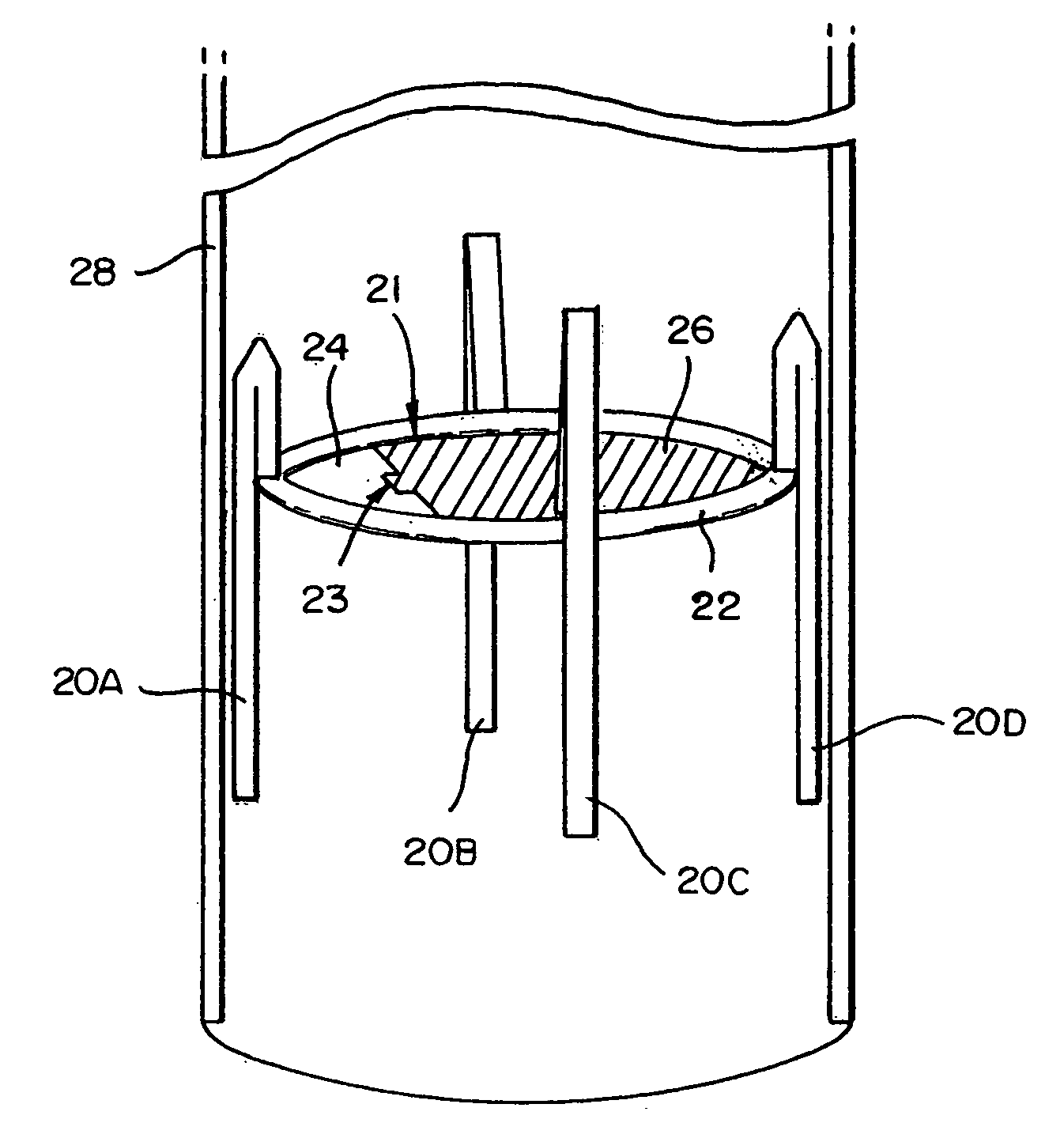
[0041] Turning now to the figures, FIG. 1 provides a three-dimensional view of the subject devices in which the device is implantable, where the device is depicted in a first, retracted position. The device shown in FIG. 1 has multiple anchoring members 20A, 20B, 20C, and 20D. Located centrally to the anchoring members 20A, 20B, 20C, and 20D, is a central rim 22. A planar element 24, fixed to the central rim 22, is connected to a movable element 26 by hinge joint 23 to form a central valve 21. The entire device, in the retracted position, is housed within a catheter 28 which allow the device to be placed at the appropriate location within the respiratory tract prior to deployment.

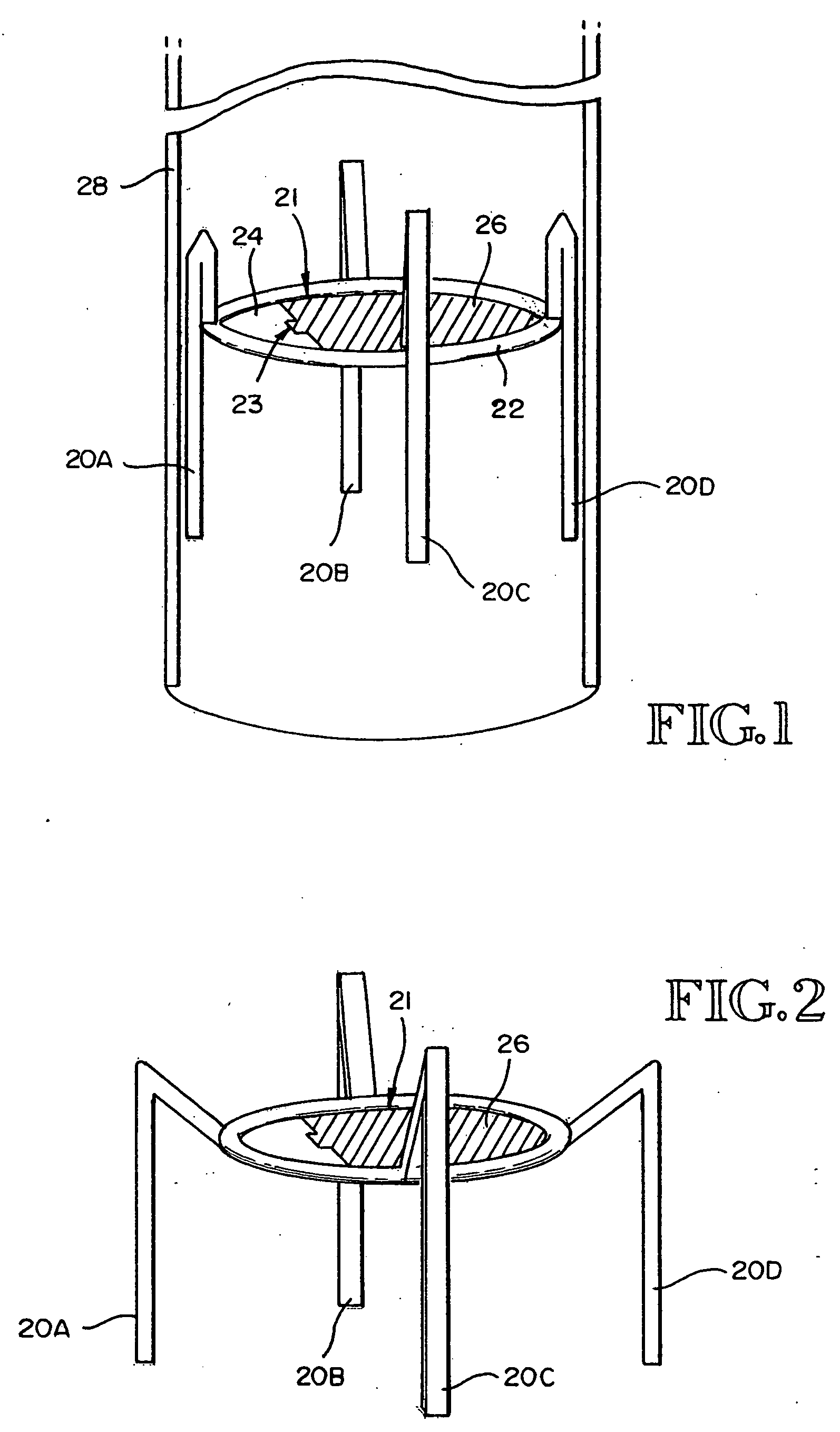
[0042]FIG. 2 provides a three-dimensional view of the device shown in FIG. 1, where the device is depicted in the deployed position with closure of the central valve 21. Anchoring members 20A, 20B, 20C, and 20D are in the deployed or non retracted position which allows the device to be anchored to the surro...

second embodiment

[0045]FIG. 5 provides a three-dimensional view of the subject devices in which the device is removable and fits within the oral cavity. In this embodiment, indentations 30 and 32 are grooves in which the user's teeth and / or gums fit, serving as a means to secure the device within the oral cavity.

[0046]FIG. 6 provides a three-dimensional view of the device shown in FIG. 5, where the device is depicted during exhalation with closure of the valve. Moveable element 36 is in the closed position and is attached to fixed element 34 via hinge 33. Fixed element 34 is also permanently attached to rim 38.

[0047]FIG. 7 provides a three-dimensional view of the device shown in FIG. 5, where the device is depicted during inhalation with inward opening of the valve, with inward opening of the moveable element 36.

[0048]FIG. 8 provides a three-dimensional view of the device shown in FIG. 5, where the device is depicted with outward deflection of the valve. This might occur during a cough, during whi...


PUM


Abstract

Methods, apparatus, and kits for enhancing breathing in patients suffering from chronic pulmonary obstructive disease are described. The methods and apparatus rely on increasing flow resistance to expiration in a manner which mimics “pursed lip” breathing which has been found to benefit patients suffering from this disease. In a first example, a device is implanted in a trachea or bronchial passage to increase flow resistance, preferably selectively increase resistance to expiration relative to inspiration. In a second embodiment, a mouthpiece is provided, again to increase resistance to expiration, preferably with a lesser increase in flow resistance to inspiration. In a third embodiment, the patient's trachea or bronchial passage is modified by the application of energy in order to partially close the lumen therethrough.

Description

RELATED APPLICATIONS [0001] This is a continuation of U.S. patent application Ser. No. 10 / 827,384, filed Apr. 19, 2004, which is a continuation of U.S. patent application Ser. No. 09 / 881,862, filed on Jun. 14, 2001 now U.S. Pat. No. 6,722,360, which claims the benefit of Provisional U.S. Patent Application Ser. No. 60 / 211,990, filed Jun. 16, 2000, the disclosures of which are incorporated herein by reference.BACKGROUND OF THE INVENTION [0002] The present invention relates generally to the field of pulmonology, and more particularly to the field of chronic obstructive pulmonary disease. In this regard, the invention provides devices and methods that are useful in improving breathing in patients with chronic pulmonary disease. [0003] Chronic obstructive pulmonary diseases (COPD) is both very common and increasing in incidence. COPD is the fourth most common cause of death in this country and the morbidity and mortality it causes continue to increase. [0004] COPD comprises chronic bron...

Claims


Application Information

Patent Timeline
IPC IPC(8): A62B7/00A62B9/02A61F2/20A61F2/24A61M16/04A61M16/06A61M16/20
CPCA61F2/20A61F2/24A61F2002/043A61M16/0488A61M16/0493A61M16/20A61M16/208A63B23/18A61M16/06A61B17/12172A61B17/12177A61B17/12036A61B17/24A61B17/12104
Inventor DOSHI, RAJIV
Owner GYRUS ACMI INC (D B A OLYMPUS SURGICAL TECH AMERICA)
Why Eureka
Try Eureka