Cyclic aeration system for submerged membrane modules

Inactive Publication Date: 2006-02-16
SINGH MANWINDER +2
View PDF30 Cites 17 Cited by
  • Summary
  • Abstract
  • Description
  • Claims
  • Application Information

AI Technical Summary

Benefits of technology

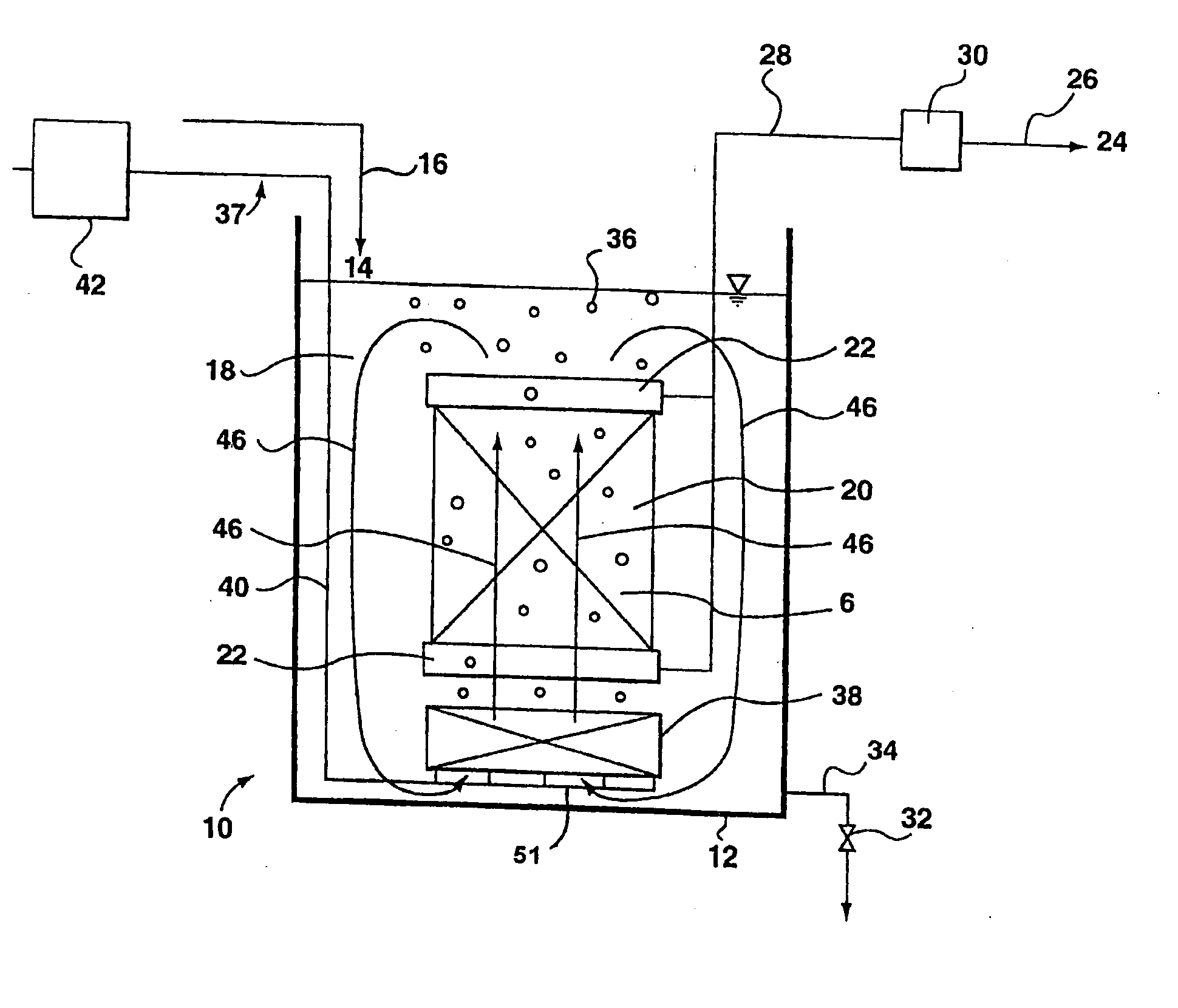
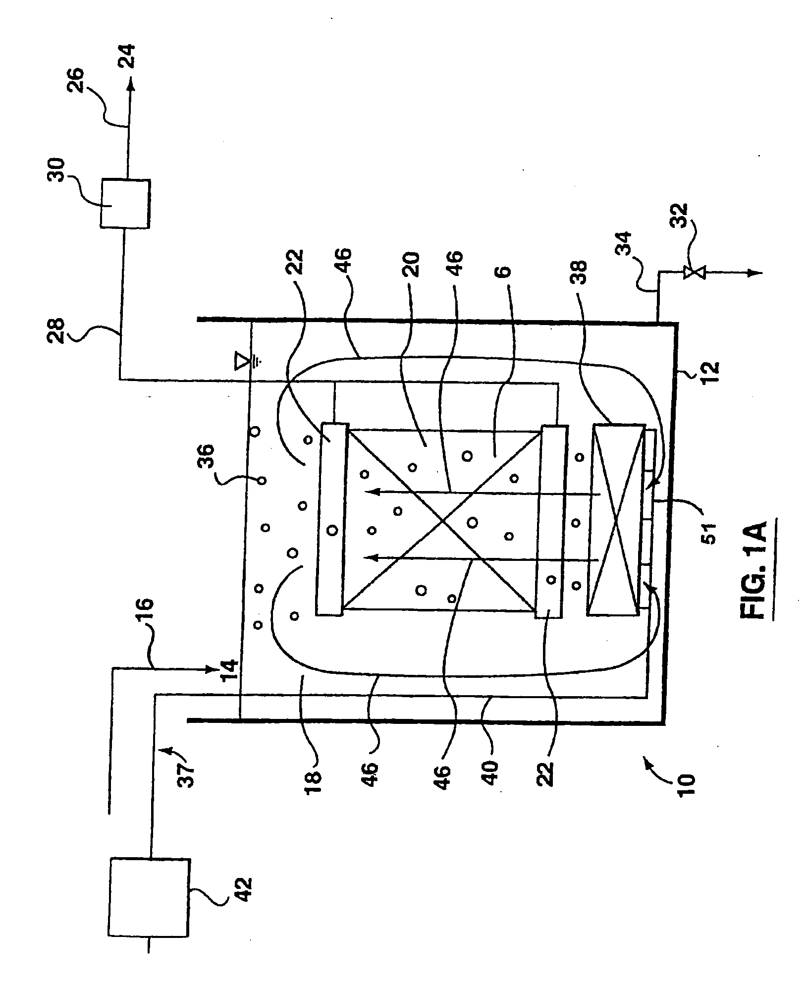
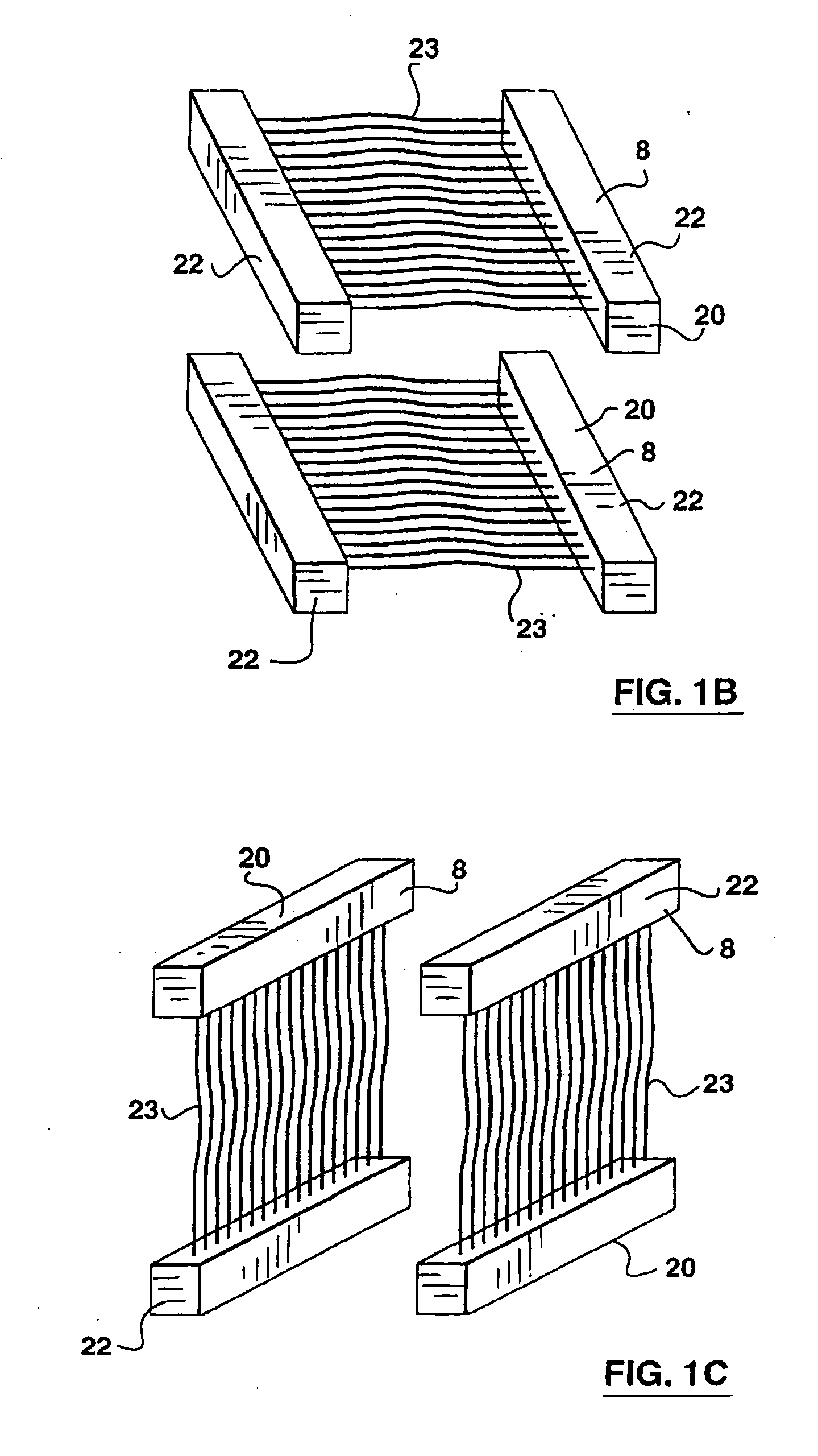
[0087] In this embodiment, having the conduit aerators 238 connected to header 251a interspersed with the conduit aerators 238 attached to header 251b creates varying areas of higher and lower density in the tank water 18 within a filtration zone. As described above, the inventors believe that these variations produce transient flow in the tank water 18. Where the effective areas of aeration above conduit aerators 238 attached to distinct branches of the air delivery network 240 are sufficiently small, however, the inventors believe that appreciable transient flow is created in a horizontal direction between areas above conduit aerators 238 attached to different branches of the air delivery network 240. Referring to FIGS. 7A, 7B, 7C, 7D the membrane modules 20 shown are preferably of the size of one or two rectangular skeins 8.
[0088] As an example, in FIGS. 8A and 8B second membrane modules 220 each made of a single rectangular skein 8 with hollow fibre membranes 23 oriented vertically aerated by a cyclic aeration system 237 with conduit aerators 238 located relative to the second membrane modules 220 as shown in FIG. 7D. In FIGS. 8A and 8B, the degree of slack of the hollow fibre membranes 23 is highly exaggerated for easier illustration. Further, only two hollow fibre membranes 23 are illustrated for each vertical rectangular skein 8 although, as discussed above, a rectangular skein 8 would actually be constructed of many hollow fibre membranes 23.
[0089] With steady state aeration, it is difficult to encourage bubbles 36 to penetrate the vertical rectangular skeins 8. The natural tendency of the bubbles 36 is to go through the areas with lowest resistance such as around the second membrane modules 220 or through slots between the second membrane modules 220 and the hollow fibre membranes 23 on the outer edge of the vertical rectangular skeins 8 may have significantly more contact with the bubbles 36. Further, the upper 10 20% of the hollow fibre membranes 23 is often forced into a tightly curved shape by the air lift effect and moves only very little. A smaller portion at the bottom of the hollow fibre membranes 23 may also be tightly curved by the current travelling around the lower header 22. In these tightly curved areas, the hollow fibre membranes 23 foul more rapidly.
[0090] With cyclic aeration, however, air at the higher rate is alternated between header 251a and header 251b. When more air is supplied to header 251a, the hollow fibre membranes 23 assume an average shape as shown in FIG. 8A with a first local recirculation pattern 380 as shown. When more air is supplied to header 251b, the hollow fibre membranes 23 assume an average shape as shown in FIG. 8B with a second local recirculation pattern 382 as shown. Under the influenc

Problems solved by technology

This technique, however, stresses the membranes and air blower motors and increases the amount of energy used which significantly increases the operating costs of the process.
With this technique, however, the rate of air flow is often below the effective range, which does not provide efficient cleaning.
This method allows for an air flow rate in the effective range but at the expense of the air blowers which wear rapidly when turned off and on frequently.
In many cases, the warranty on the air blower is voided by such intermittent operation.
The membranes in these dead zones, or the parts of the membranes in these dead zones, are not effectively cleaned and may be operating in water having a higher concentration of solids than in the tank water generally.
Accordingly, these mem

Method used


Image

  • Cyclic aeration system for submerged membrane modules
  • Cyclic aeration system for submerged membrane modules
  • Cyclic aeration system for submerged membrane modules

Examples


Example

Example 1

[0113] A cassette of 8 ZW 500 membrane modules were operated in bentonite suspension under generally constant process parameters but for changes in flux and aeration. A fouling rate of the membranes was monitored to assess the effectiveness of the aeration. Aeration was supplied to the cassette at constant rates of 204 m3 / h (ie. 25.5 m3 / h per module) and 136 m3 / h and according to various cycling regimes. In the cycled tests, a total air supply of 136 m3 / h was cycled between aerators located below the modules and aerators located between and beside the modules in cycles of the durations indicated in FIG. 10A. Aeration at 136 m3 / h in 30 second cycles (15 seconds of air to each set of aerators) was approximately as effective as non-cycled aeration at 204 m3 / h.

Example

Example 2

[0114] The same apparatus as described in example 1 was tested under generally constant process parameters but for the variations in air flow indicated in FIG. 10B. In particular, 70% of the total air flow of 136 m3 / h was cycled in a 20 second cycle such that each group of aerators received 70% of the total airflow for 10 seconds and 30% of the total airflow for 10 seconds. As shown in FIG. 10B, cycling 70% of the air flow resulted in reduced fouling rate at high permeate flux compared to constant aeration at the same total air flow.

Example

Example 3

[0115] 2 ZW 500 membrane modules were operated to produce drinking water from a natural supply of feed water. Operating parameters were kept constant but for changes in aeration. The modules were first operated for approximately 10 days with non-cycled aeration at 25.5 m3 / h per module (for a total system airflow 51 m3 / h). For a subsequent period of about three days, air was cycled from aerators near one set of modules to aerators near another set of modules such that each module was aerated at 12.8 m3 / h for 10 seconds and then not aerated for a period of 10 seconds (for a total system airflow of 12.8 m3 / h). For a subsequent period of about 10 days, the modules were aerated such that each module was aerated at 25.5 m3 / h for 10 seconds and then not aerated for a period of 10 seconds (for a total system airflow of 25.5 m3 / h). For a subsequent period of about 10 days, the initial constant airflow was restored. As shown in FIG. 10C, with aeration such that each module was aerat...


PUM

PropertyMeasurementUnit
Lengthaaaaaaaaaa
Flow rateaaaaaaaaaa
Timeaaaaaaaaaa

Abstract

An aeration system for a submerged membrane module has a set of aerators connected to an air blower, valves and a controller adapted to alternately provide a higher rate or air flow and a lower rate of air flow in repeated cycles. In an embodiment, the air blower, valves and controller, simultaneously provide the alternating air flow to two or more sets of aerators such that the total air flow is constant, allowing the blower to be operated at a constant speed. In another embodiment, the repeated cycles are of short duration. Transient flow conditions result in the tank water which helps avoid dead spaces and assists in agitating the membranes.

Description

[0001] This is a continuation of U.S. application Ser. No. 10 / 680,145 filed Oct. 8, 2003, which is an application claiming the benefit under 35 USC 119(e) of Provisional Application No. 60 / 417,560, filed Oct. 11, 2002 and a continuation-in-part of U.S. patent application Ser. No. 10 / 369,699, filed Feb. 21, 2003, which is a continuation of U.S. application Ser. No. 09 / 814,737, filed Mar. 23, 2001, issued as U.S. Pat. No. 6,550,747 on Apr. 22, 2003, which is a continuation-in-part of U.S. application Ser. No. 09 / 488,359, filed Jan. 19, 2000, issued as U.S. Pat. No. 6,245,239 on Jun. 12, 2001, which is a continuation of international application number PCT / CA99 / 00940, filed Oct. 7, 1999, which is an application claiming the benefit under 35 USC 119(e) of Provisional Application Nos. 60 / 103,665, filed Oct. 9, 1998 and 60 / 116,591, filed Jan. 20, 1999, both abandoned. All of U.S. application Ser. Nos. 10 / 680,145 filed Oct. 8, 2003; 10 / 369,699; 09 / 814,737; 09 / 488,359; 60 / 103,665 filed Oct....

Claims


Application Information

Patent Timeline
IPC IPC(8): B01F3/04B01D61/18B01D63/02B01D63/04B01D65/02B01D65/08B01F33/40C02F1/44C02F1/74C02F3/12C02F3/20
CPCB01D61/18B01D2313/26B01D63/024B01D63/026B01D63/043B01D65/02B01D65/08B01D2315/06B01D2321/04B01D2321/185B01D2321/2066B01F3/04113B01F3/04439B01F13/0266B01F2003/04148B01F2003/04319B01F2003/04361B01F2215/0052C02F1/444C02F1/74C02F3/1273C02F3/201C02F5/00B01D2313/18B01D63/02Y02W10/10B01F23/23105B01F23/23113B01F23/231231B01F23/2319B01F23/231265B01F33/4062B01F2101/305B01F23/231242
Inventor SINGH, MANWINDERCOTE, PIERRE LUCIENRABIE, HAMID R.
Owner SINGH MANWINDER
Why Eureka
Try Eureka