Method and system for circular polarization correction for independently moving GNSS antennas

a technology of gnss antennas and antennas, applied in the field of methods and systems for circular polarization correction of independently moving gnss antennas, can solve problems such as limited systems, and achieve the effect of high accuracy

Active Publication Date: 2006-02-16
INTEGRINAUTICS
View PDF29 Cites 17 Cited by
  • Summary
  • Abstract
  • Description
  • Claims
  • Application Information

AI Technical Summary

Benefits of technology

[0027] In a specific embodiment, the mobile unit and base station form a survey system that can locate the position of the base station and the mobile unit to a high accuracy in three-dimensional space. The advantage of the present embodiment is that only one of the base station and mobile unit is required to see four satellites in order to resolve its position. That is, if one of the units only receives carrier signals from three satellites, position can still be resolved to the accuracies provided by kinematic GPS systems.

Problems solved by technology

The problem with existing single receiver, common clock, multiple-antenna DGPS systems, however, is that they assume that there are no changes in relative antenna attitude between measurements.
Thus, these systems have been limited to applications in which all of the antennas are fixed to a common rigid or semirigid body, such as orientation determination.

Method used


Image

  • Method and system for circular polarization correction for independently moving GNSS antennas
  • Method and system for circular polarization correction for independently moving GNSS antennas
  • Method and system for circular polarization correction for independently moving GNSS antennas

Examples


Embodiment Construction

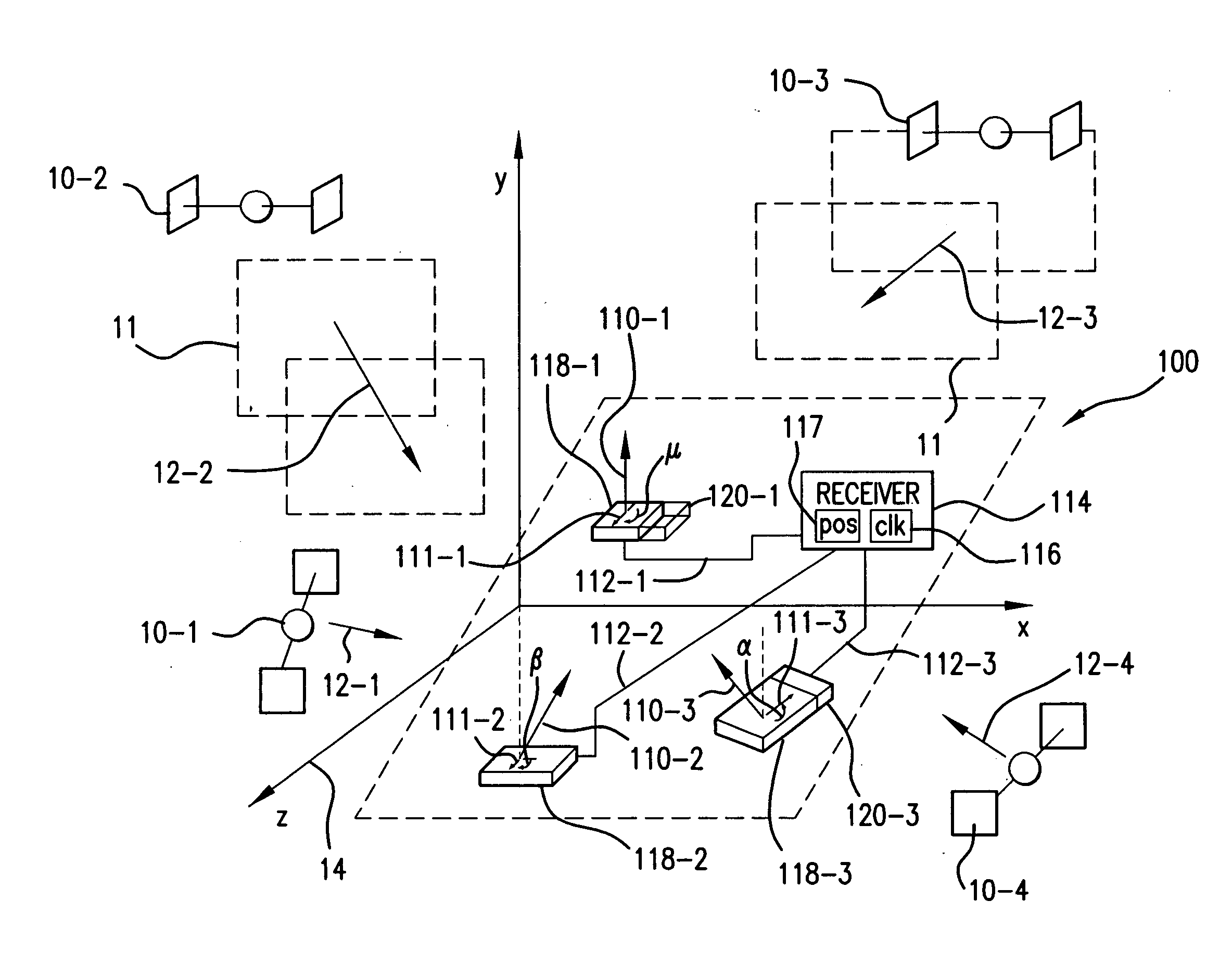
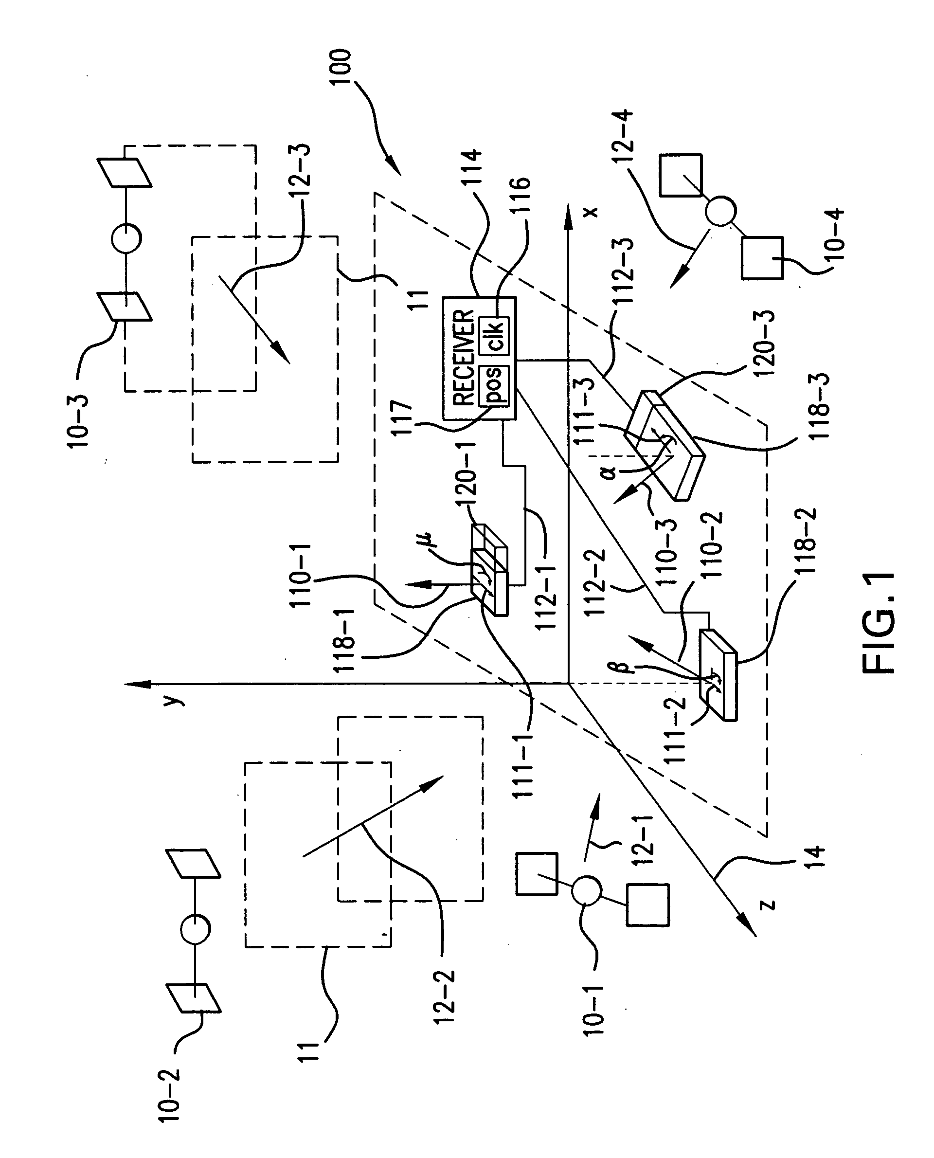
[0045]FIG. 1 is a schematic diagram illustrating a position detection system 100 that has been constructed according to the principles of the present invention.

[0046] In more detail, a number of satellites are provided by the global positioning system (10-1, 10-2, 10-3, and 10-4). In the preferred embodiment, these GPS satellites are satellites of the NAVSTAR, GLONASS, and / or Galileo systems. They each broadcast carrier signals 12-1, 12-2, 12-3, and 12-4 to enable receiver antenna systems to determine their position in a three-dimensional space represented by the x, y, and z coordinate axes 14.

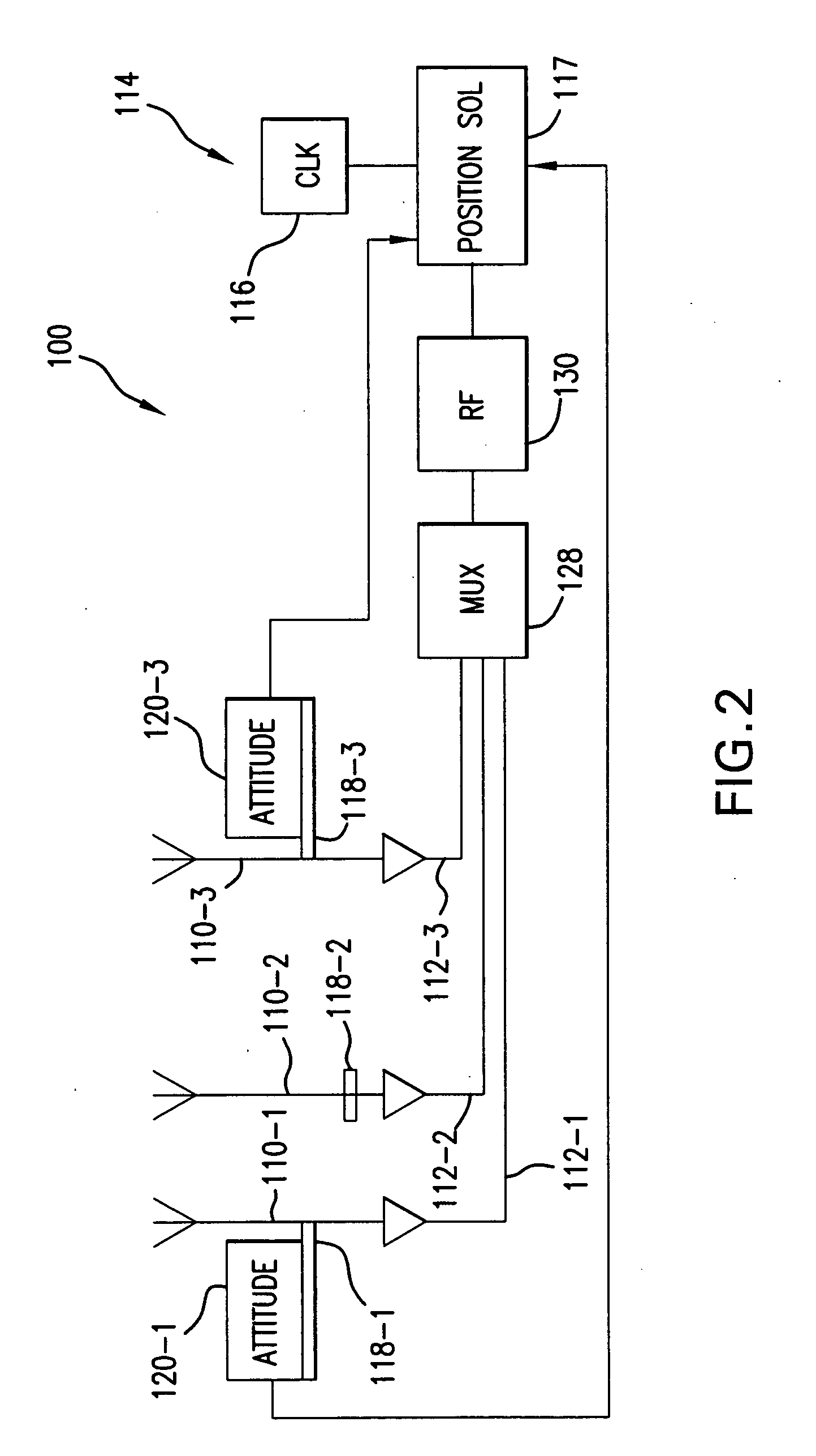
[0047] The present invention is especially relevant to DGPS and kinematic GPS systems, in which carrier signal information is detected by multiple antennas but processed by a single receiver and in response to a common clock signal that is generated by the receiver 114.

[0048] Specifically, in the illustrated embodiment, antennas 110-1, 110-2, and 110-3 are located in the coordinate space 14...


PUM


Abstract

A system and method for compensating for changes in relative antenna attitude in a single-receiver position detection system, such as a differential carrier phase GPS system, utilizes sensor input to detect changes in the relative attitude of at least two antennas or an antenna positioner, such as an motorized actuator or operator, that orients or re-orients the antennas to a predetermined orientation. The changes in the detected relative carrier phase due to the right hand circular polarized nature of the carrier signals are thus corrected. In this way, the high positional accuracy associated with kinematic GPS systems, for example, can be achieved even when the system's antennas are not constrained by a common rigid body, for example.

Description

BACKGROUND OF THE INVENTION [0001] The NAVSTAR Global Positioning System (GPS) is a satellite-based navigation system developed by the U.S. military in the 1970's. The GPS space segment consists of a nominal constellation of 24 satellites, four satellites in each of 6 orbit planes. [0002] Originally conceived as a navigation aid for ships, the use of the system has become ubiquitous both within the military and within civilian and commercial applications. For example, many cars today are outfitted with GPS navigation systems that locate the car on a displayed digital map to the driver. In commercial applications, GPS systems are used for surveying in addition to controlling vehicles such as graders during the laying of road beds. On these vehicles, the antennas are sometimes located on the blade in addition to the cab. In order to ensure good satellite visibility, however, the antennas must be placed on high poles to provide line of sight to the required four satellites. [0003] The ...

Claims


Application Information

Patent Timeline
Patent Type & Authority Applications(United States)
IPC IPC(8): G01S5/14G01S19/44G01S19/46
CPCH01Q1/1257
Inventor LAWRENCE, DAVID GARYO'CONNOR, MICHAEL L.
Owner INTEGRINAUTICS
Why Eureka
Try Eureka