
Liquid crystal display device

a liquid crystal display and display device technology, applied in the field of white light sources, can solve the problems of reducing color reproducibility, conceivable response delay in a ccfl, and insufficient brightness, and achieve the effect of satisfying moving picture characteristics, color reproducibility and reliability

Active Publication Date: 2006-02-16
PANASONIC LIQUID CRYSTAL DISPLAY CO LTD +1
View PDF14 Cites 29 Cited by
  • Summary
  • Abstract
  • Description
  • Claims
  • Application Information

AI Technical Summary

Benefits of technology

[0023] An object of the present invention is to provide a liquid crystal display device, such as a liquid crystal TV, for displaying a moving picture in which no blurred image is produced. More particularly, in a moving picture displayable liquid crystal display device, to improve the response of a green phosphor used in a white light source, thereby attaining satisfactory moving picture characteristics, color reproducibility and reliability, simultaneously, the present invention employs the following means. Furthermore, the present invention improves the response of a red phosphor by the following means, thereby attaining satisfactory high-speed response, color reproducibility and reliability at the same time.
[0057] By virtue of the aforementioned means, the present invention successfully provides a moving picture displayable liquid crystal display device simultaneously attaining satisfactory moving picture characteristics, color reproducibility and reliability.

Problems solved by technology

However, actually in a CCFL, the brightness does not sufficiently go along with the change of the timing signal Vsig and follows with a time lag (FIG. 5(c)).
Such a response delay in a CCFL is conceivably caused by delay of an inverter circuit supplying power to the CCFL, response of ultraviolet light generated within the CCFL, and response of phosphors.
However, in applying SrAl2O4: Eu to a CCFL, there are the flowing two big problems.
A first problem is a reduction of color reproducibility, more specifically, it is primarily due to a reduction of blue chromaticity.
A second problem is a decrease of reliability (brightness deterioration).
The human vision is said to be sensible enough to recognize a change of Δ (u,v)=0.2 or more, so that such a shift of blue chromaticity is a significant problem.
The second problem is the reliability of SrAl2O4:Eu.
A liquid crystal display device formed of such a chemically labile material cannot ensure the reliability.
However, a green phosphor material LaPO4: Tb, Ce presently in use has a problem in response characteristics, whereas SrAl2O4: Eu has big problems in color reproducibility and reliability.
In short, a liquid crystal display device satisfying all three characteristics: moving picture characteristics (in particular, CCFL response characteristics), color reproducibility and reliability cannot be obtained by use of conventional techniques.

Method used


Image

  • Liquid crystal display device
  • Liquid crystal display device
  • Liquid crystal display device

Examples


example 1

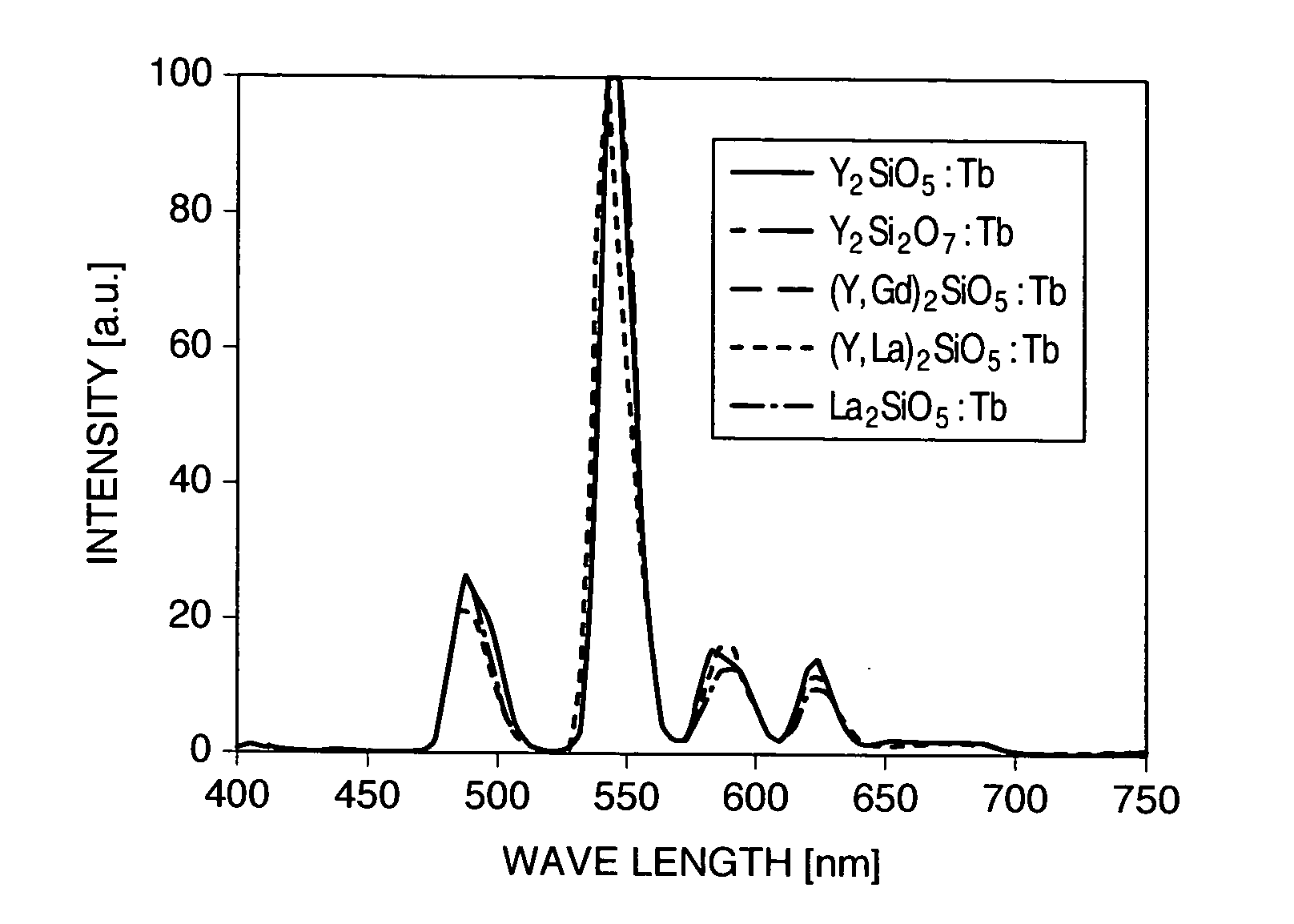
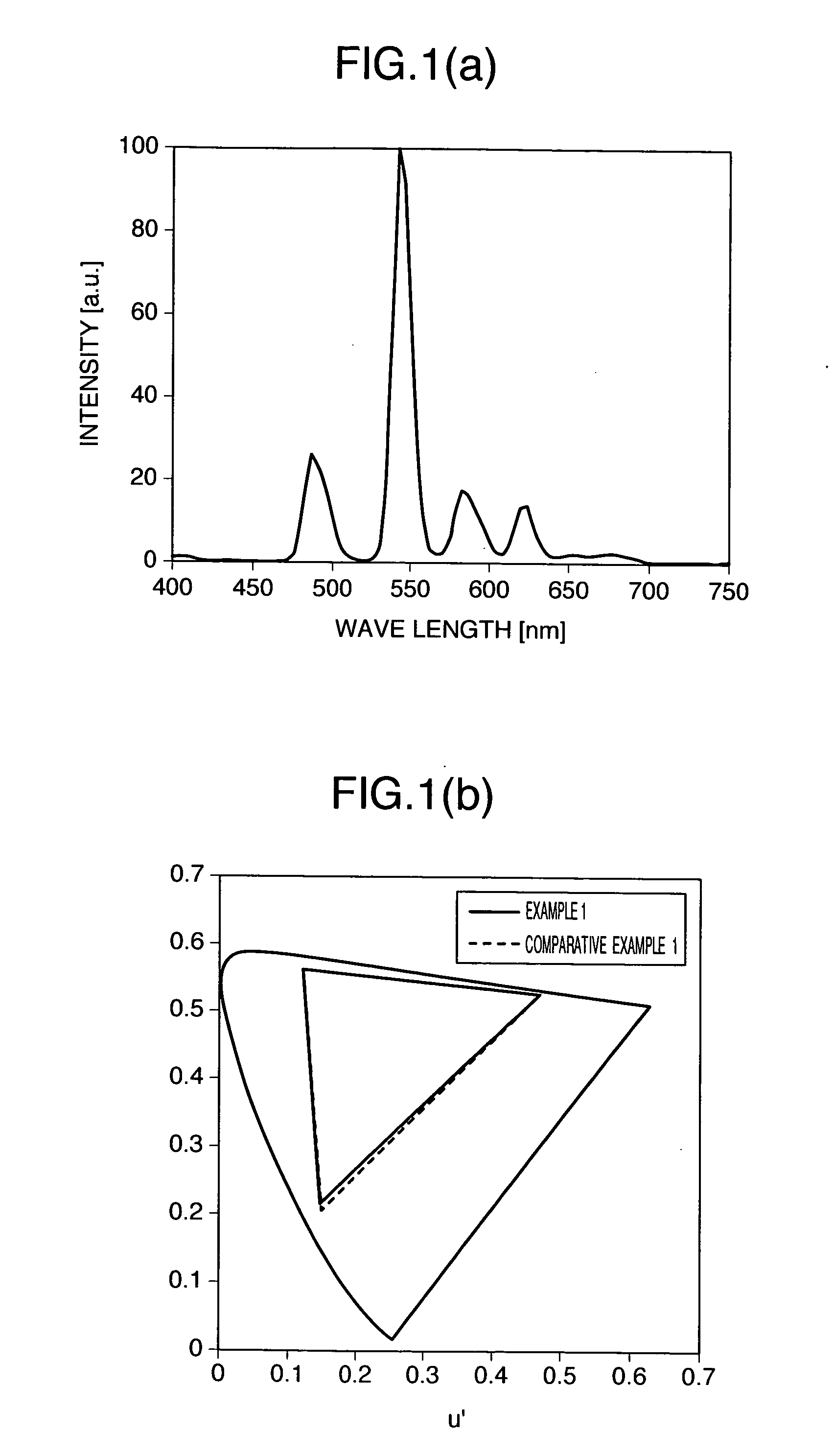
[0130] The liquid crystal display device of this Example has the same structure as that of a conventional one. The schematic structure is shown in FIG. 2. What is different from the conventional one is a green phosphor material used in CCFL. In this Example, a green phosphor mixture is used as a green phosphor, more specifically, a mixture of LaPO4: Tb, Ce and Y2SiO5; Tb, Ce is used. Now, a process for manufacturing a CCFL using these phosphors and a process for manufacturing a liquid crystal display device using the CCFL will be described.

[0131] A CCFL is generally manufactured in accordance with steps shown in FIG. 11. The structure of the CCFL manufactured is shown in FIG. 3(a). First, a binding agent such as alumina and phosphor materials are mixed in an organic solvent called a vehicle. In this Example, as a blue phosphor and a red phosphor, conventional BaMgAl10O17: Eu and Y2O3: Eu are used, respectively. As a green phosphor, a green phosphor mixture of LaPO4: Tb, Ce and Y2Si...

example 2

[0139] This Example differs from Example 1 in the green phosphor mixture to be used; however, other constitutions are the same as in Example 1. In this Example, as the green phosphor mixture, a mixture of LaPO4: Tb, Ce and Y3Al5O12: Tb, Ce is used. The mixing ratio of LaPO4: Tb, Ce to Y3Al5O12: Tb, Ce is 0.1 to 0.9 on a molar basis.

[0140] The emission spectrum of the green phosphor mixture is shown in FIG. 12(a). The spectrum has substantially the same as that of LaPO4: Tb, Ce conventionally used. The response characteristics are τon=2.8 msec and τoff=4.0 msec, which are reduced to about 60% of a conventional LaPO4: Tb, Ce.

[0141] The color gamut of the liquid crystal display device obtained in this Example is shown in FIG. 12(b). The color gamut is substantially the same as that of Comparative Example 1 described later. The chromaticity change of a blue color is as extremely small as Δu′, v′=0.008, which is lower than a visual detection ability of a human (Δu′, v′<0.02).

[0142] Th...

example 3

[0143] This Example differs from Example 1 in the green phosphor mixture to be used; however, other constitutions are the same as in Example 1. In this Example, as the green phosphor mixture, a mixture of LaPO4: Tb, Ce and LaOCL: Tb, Ce is used. The mixing ratio of LaPO4: Tb, Ce to LaOCL: Tb, Ce is 0.3 to 0.7 on a molar basis.

[0144] The emission spectrum of the green phosphor mixture is shown in FIG. 13(a). The spectrum has substantially the same as that of LaPO4: Tb, Ce conventionally used. The response characteristics are τon=2.4 msec and τoff=3.0 msec, which are reduced to about 50% of a conventional LaPO4: Tb, Ce.

[0145] The color gamut of the liquid crystal display device obtained in this Example is shown in FIG. 13(b). The color gamut is substantially the same as that of Comparative Example 1 described later. The chromaticity change of a blue color is as extremely small as Δu′, v′=0.001, which is lower than a visual detection ability of a human (Δu′, v′<0.02).

[0146] The liqu...


PUM


Abstract

An object of the present invention is to provide a moving picture displayable liquid crystal display device capable of attaining satisfactory moving picture characteristics, color reproducibility and reliability at the same time. A liquid crystal display device according to the present invention comprises a white light source having a blue phosphor, a green phosphor, and a red phosphor and having a light-on state and a light-off state in a single frame; and a liquid crystal display panel which controls an amount of transmitted light from the white light source for each pixel, and which has a color filter for allowing one of blue light, green light, and red light to be transmitted therethrough for each pixel, in which at least one type of the blue color phosphor, green color phosphor, and red color phosphor is a phosphor mixture composed of at least two phosphors having different host material composition, and phosphors having a luminescence center of the same element are used for the phosphor mixture of the same color.

Description

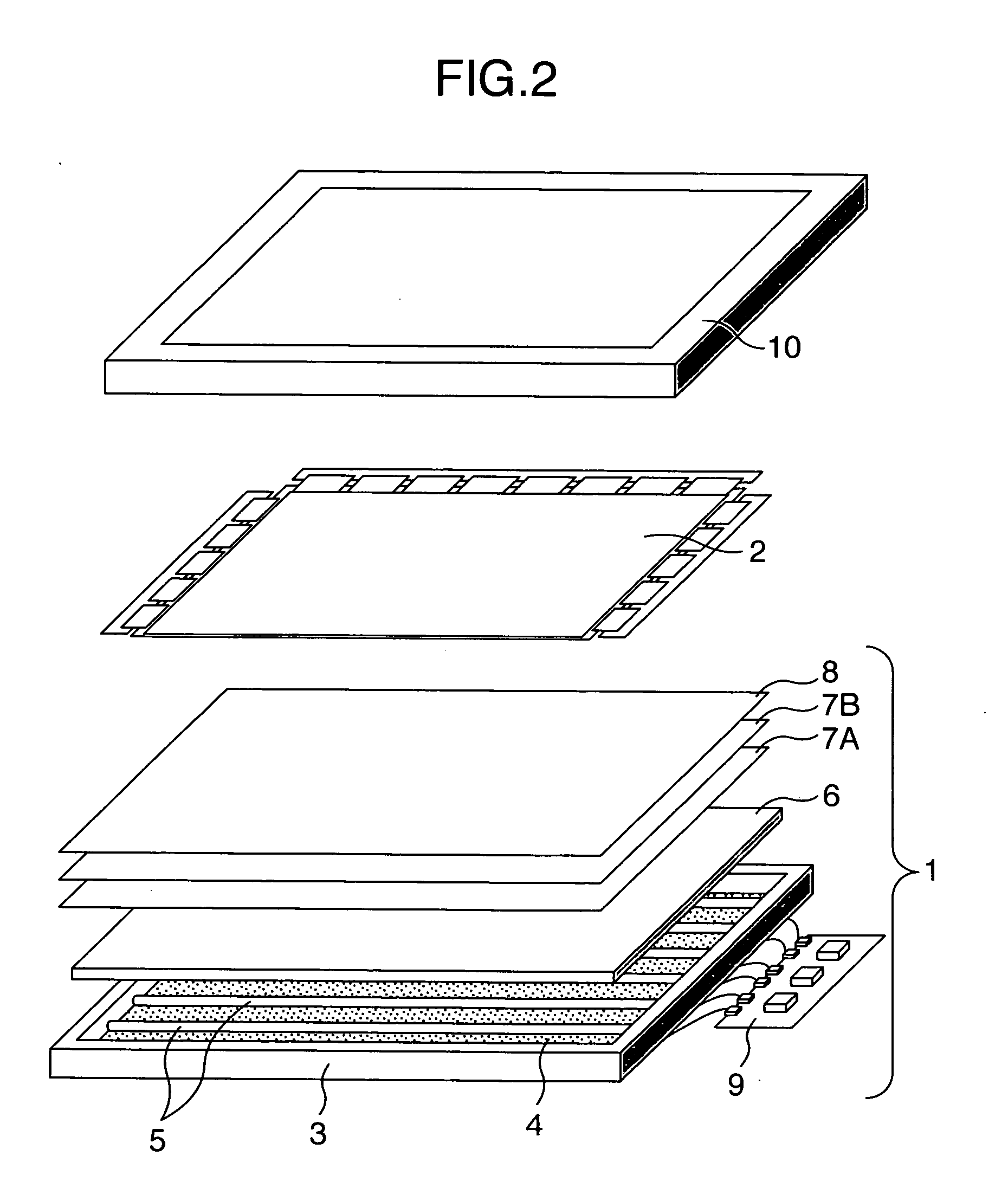
INCORPORATION BY REFERENCE [0001] The present application claims priority from Japanese application JP 2004 1843283 filed on Jun. 23, 2004, the content of which is hereby incorporated by reference into this application. BACKGROUND OF THE INVENTION [0002] The present invention relates to a white light source having a phosphor mixture provided therein and a liquid crystal display device using the same. [0003] The liquid crystal display device is constituted of a back light unit 1 and a liquid crystal display panel 2, as shown in FIG. 2. The back light unit is further composed of a white light source (cold cathode fluorescent lamp 5 in FIG. 2), an inverter 9 for driving the white light source, a reflector 4, a metal case 3, a diffuser plate 6, prism sheets 7 (7A, 7B) and a reflective polarizer 8. [0004] As the white light source used in the liquid crystal display device, a three band-type cold cathode fluorescent lamp (CCFL) 5 is generally used. The structure of the CCFL is as shown in...

Claims


Application Information

Patent Timeline
IPC IPC(8): G02F1/1335G02F1/13357
CPCG02F1/133609G02F1/133604
Inventor OKISHIRO, KENJIIMAMURA, SHINSHIIKI, MASATOSHI
Owner PANASONIC LIQUID CRYSTAL DISPLAY CO LTD
Learn More