Cogeneration system

Inactive Publication Date: 2006-02-23
LG ELECTRONICS INC
View PDF6 Cites 5 Cited by
  • Summary
  • Abstract
  • Description
  • Claims
  • Application Information

AI Technical Summary

Benefits of technology

[0025] Since the cogeneration system of the present invention includes a separate outdoor heat exchanger to receive waste heat from an engine during a heati

Problems solved by technology

However, since the waste heat generated from the gas engine 1 is used only to pre-heat the outdoor heat exchanger 25 through the air pre-heati

Method used


Image

  • Cogeneration system
  • Cogeneration system
  • Cogeneration system

Examples


Embodiment Construction

[0031] Hereinafter, exemplary embodiments of a cogeneration system according to the present invention will be described with reference to the annexed drawings.

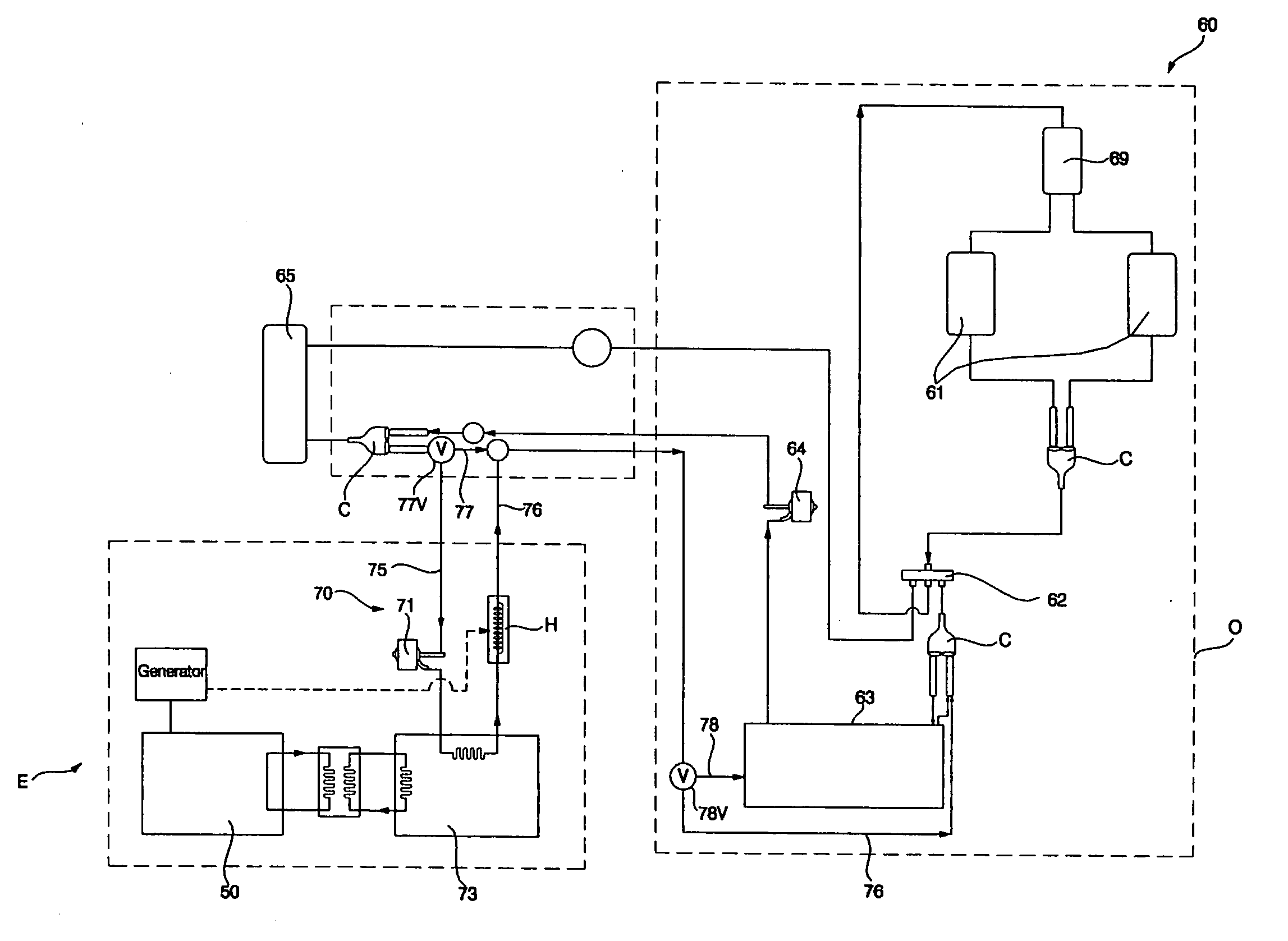
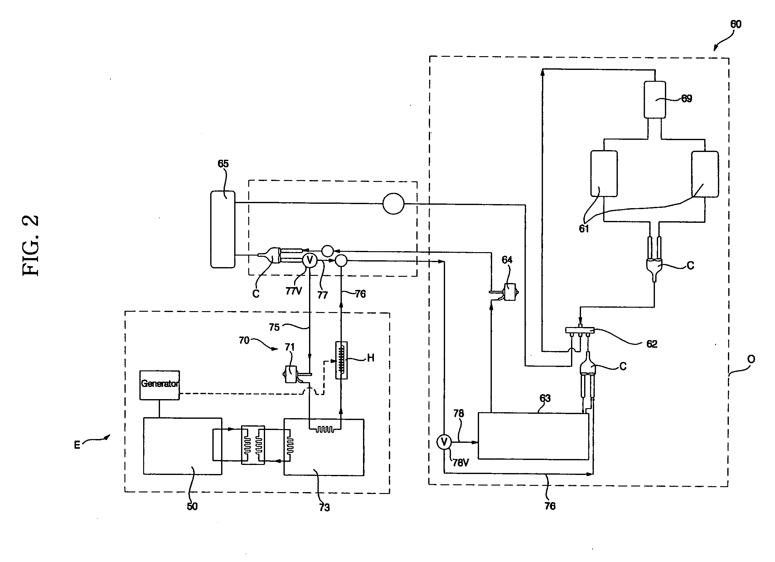
[0032]FIG. 2 is a schematic configuration diagram illustrating a cogeneration system according to an exemplary embodiment of the present invention. FIG. 3 is a schematic configuration diagram illustrating an engine room included in the cogeneration system.

[0033] As shown in FIG. 2, the cogeneration system includes an engine 50 to drive a generator 52, and thus, to generate electricity, and a cooling / heating unit 60. The cooling / heating unit 60 uses a heat pump type refrigerant cycle, in which a refrigerant is circulated through at least one compressor 61, a four-way valve 62, a first outdoor heat exchanger 63, a first expansion device 64, and an indoor heat exchanger 65, in this order, during a cooling operation of the cogeneration system. The cogeneration system also includes a waste heat consuming heating unit 70. The wast...


PUM


Abstract

A cogeneration system including an engine, which drives a generator to generate electricity, a cooling/heating unit using a heat pump type refrigerant cycle, in which a refrigerant is circulated through at least one compressor, a four-way valve, a first outdoor heat exchanger, a first expansion device, and an indoor heat exchanger, in this order, during a cooling operation of the cogeneration system, and a waste heat consuming heating unit using a refrigerant cycle, in which the refrigerant is circulated through the compressor, the four-way valve, the indoor heat exchanger, a second expansion device, and a second outdoor heat exchanger to be heated by waste heat of the engine, in this order, during a heating operation of the cogeneration system. In accordance with the cogeneration system, it is possible to maximize utilization of engine waste heat during the heating operation and to achieve an enhancement in heating performance.

Description

BACKGROUND OF THE INVENTION [0001] 1. Field of the Invention [0002] The present invention relates to a cogeneration system in which both the electricity and waste heat generated from an engine are used, and, more particularly, to a cogeneration system which includes a separate outdoor heat exchanger to be heated by waste heat of an engine during a heating operation, thereby achieving an enhancement in heating performance. [0003] 2. Description of the Related Art [0004] In general, cogeneration systems are adapted to generate both electricity and heat from a single energy source. [0005] Such a cogeneration system can recover heat of exhaust gas or waste heat of cooling water generated from an engine or turbine during an electricity generation operation, so that the cogeneration system can achieve an increase in energy efficiency of 70 to 80% over other systems. By virtue of such an advantage, the cogeneration system has recently been highlighted as an electricity and heat supply sour...

Claims


Application Information

Patent Timeline
IPC IPC(8): F25B27/00F25B13/00
CPCF25B13/00F25B27/02F25B30/06Y02E20/14F25B2400/075F25B2500/02F25B2700/2106F25B2313/02523Y02P80/15Y02A30/274F02C6/18
Inventor KANG, SEUNG TAKCHOI, CHANG MINCHOI, WON JAELIM, HYUNG SOOHWANG, YOON JEI
Owner LG ELECTRONICS INC
Why Eureka
Try Eureka