Parametrically disciplined operation of a vibratory gyroscope

Active Publication Date: 2006-02-23
CALIFORNIA INST OF TECH +1
View PDF35 Cites 39 Cited by
  • Summary
  • Abstract
  • Description
  • Claims
  • Application Information

AI Technical Summary

Benefits of technology

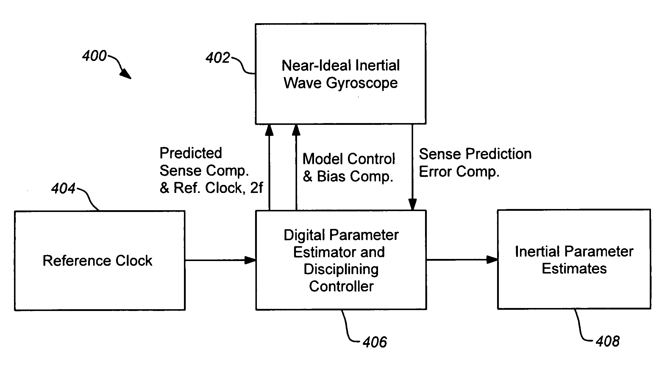
[0027] Embodiments of the present invention adapt the principle of parametric driving of oscillators to the operation of a microgyroscope to facilitate complete discipline of the parameters of motion, improve performance and other characteristics. Parametric driving, where the resonator spring constant is modulated at twice the resonant fre

Problems solved by technology

However, their performance so far has been unsatisfactory for inertial positioning, pointing or autonomous navigation.
This goal has been difficult to achieve for small devices capable of being mass produced.
The extreme stability of the shape (sub parts per million), and hence the rate scale factor, has not yet been achieved in practice by any vibratory gyroscope even today.
Limitations in design, fabricated mechanical precision and quality and subsequent electronics operation have further resulted in high drift and noise that hinder the achievement of ideal inertial wave-based operation and performance.
Conventionally-machined gyroscopes suitable for inertial wave operation such as the quartz hemispherical resonator gyroscope (HRG) have an ideal axisymmetric design, finite angular gain, k=0.3, with near-ideal mechanical fabrication precision and quality, but are not compact, low-cost and low-power.
Furthermore, the HRG electronics operation limits performance.
Failure to discipline all parameters necessitates expensive calibration of the final rate output bias over temperature and case-orientation of the vibration pattern due to changes in the undisciplined parameters.
Further, the output disturbance noise of the closed loop electronics of the HRG design is limiting noise and drift per

Method used


Image

  • Parametrically disciplined operation of a vibratory gyroscope
  • Parametrically disciplined operation of a vibratory gyroscope
  • Parametrically disciplined operation of a vibratory gyroscope

Examples


Embodiment Construction

[0046] In the following description of the preferred embodiment, reference is made to the accompanying drawings which form a part hereof, and in which is shown by way of illustration a specific embodiment in which the invention may be practiced. It is to be understood that other embodiments may be utilized and structural changes may be made without departing from the scope of the present invention.

1.0 Overview

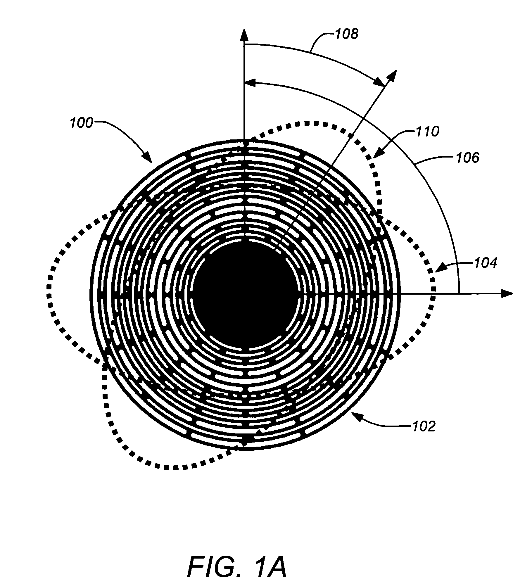
[0047] As mentioned above, G. H. Bryan was the first to identify the existence of a traveling elastic inertial wave in a rotating axisymmetric shell and that it always traveled at a precise geometrically determined fraction of the inertial rotation rate, Ω. In a hemisphere for example, the inertial wave travels in a retrograde direction at 0.3 Ω for a rotating observer. As the art of micromachining has advanced and the precision and mechanical quality of the resulting structures has improved it is presently possible to fabricate a nearly-ideal inertial wave gyroscope. Furthe...


PUM

PropertyMeasurementUnit
Frequencyaaaaaaaaaa
Erroraaaaaaaaaa

Abstract

Parametrically disciplined operation of a symmetric nearly degenerate mode vibratory gyroscope is disclosed. A parametrically-disciplined inertial wave gyroscope having a natural oscillation frequency in the neighborhood of a sub-harmonic of an external stable clock reference is produced by driving an electrostatic bias electrode at approximately twice this sub-harmonic frequency to achieve disciplined frequency and phase operation of the resonator. A nearly symmetric parametrically-disciplined inertial wave gyroscope that can oscillate in any transverse direction and has more than one bias electrostatic electrode that can be independently driven at twice its oscillation frequency at an amplitude and phase that disciplines its damping to zero in any vibration direction. In addition, operation of a parametrically-disciplined inertial wave gyroscope is taught in which the precession rate of the driven vibration pattern is digitally disciplined to a prescribed non-zero reference value.

Description

CROSS-REFERENCE TO RELATED APPLICATIONS [0001] This application claims the benefit under 35 U.S.C. §119(e) of the following U.S. provisional patent application, which is incorporated by reference herein: [0002] U.S. Provisional Patent Application No. 60 / 592,589, filed Jul. 29, 2004, and entitled “PARAMETRICALLY DISCIPLINED SYMMETRIC NEARLY DEGENERATE MODE VIBRATORY GYROSCOPE”, by Shcheglov et al. [0003] This application is related to the following co-pending patent applications, which are all incorporated by reference herein: [0004] U.S. patent application Ser. No. 10 / 639,134, by Shcheglov et al., filed Aug. 12, 2003, and entitled “ISOLATED PLANAR GYROSCOPE WITH INTERNAL RADIAL SENSING AND ACTUATION,” which claims priority to U.S. Provisional Patent Application No. 60 / 402,681, filed Aug. 12, 2002, and entitled “CYLINDER GYROSCOPE WITH INTEGRAL SENSING AND ACTUATION”, by Shcheglov et al. and U.S. Provisional Patent Application No. 60 / 428,451, filed Nov. 22, 2002, and entitled “DESIGN...

Claims


Application Information

Patent Timeline
IPC IPC(8): G01C19/56G01C25/00
CPCG01C19/5684Y10T29/49009Y10T74/1229
Inventor SHCHEGLOV, KIRILL V.HAYWORTH, KEN J.CHALLONER, A. DORIANPEAY, CHRIS S.
Owner CALIFORNIA INST OF TECH
Why Eureka
Try Eureka