Current-limited protection circuit of switching power converter

a protection circuit and power converter technology, applied in the direction of electric variable regulation, process and machine control, instruments, etc., can solve the problems of high manufacturing cost, complicated methods, and disadvantages of prior art switching power converters, and achieve the effects of reducing power consumption, low resistance, and shrinking circuit siz

Active Publication Date: 2006-02-23
NAT CHUNG SHAN INST SCI & TECH
View PDF4 Cites 12 Cited by
  • Summary
  • Abstract
  • Description
  • Claims
  • Application Information

AI Technical Summary

Benefits of technology

[0018] Accordingly, the present invention uses the amplifier for amplifying the induced voltage dropped on these two terminals of the first capacitor. Without a great induced voltage, the output of the pulse-width modulator can be controlled so as to control the working current. With the requirement of a low induced voltage, the resistor can have a low resistance so as to reduce power consumptions and shrink the size of circuit. By modifying the gain of the amplifier, the induced voltage can be amplified. Therefore, the present invention is adapted for various pulse-width modulators.

Problems solved by technology

However, the prior art switching power converter has disadvantages.
For fabricating a resistor with a precise and small resistance, the manufacturing costs increase.
The method is complicated.

Method used


Image

  • Current-limited protection circuit of switching power converter
  • Current-limited protection circuit of switching power converter
  • Current-limited protection circuit of switching power converter

Examples


Embodiment Construction

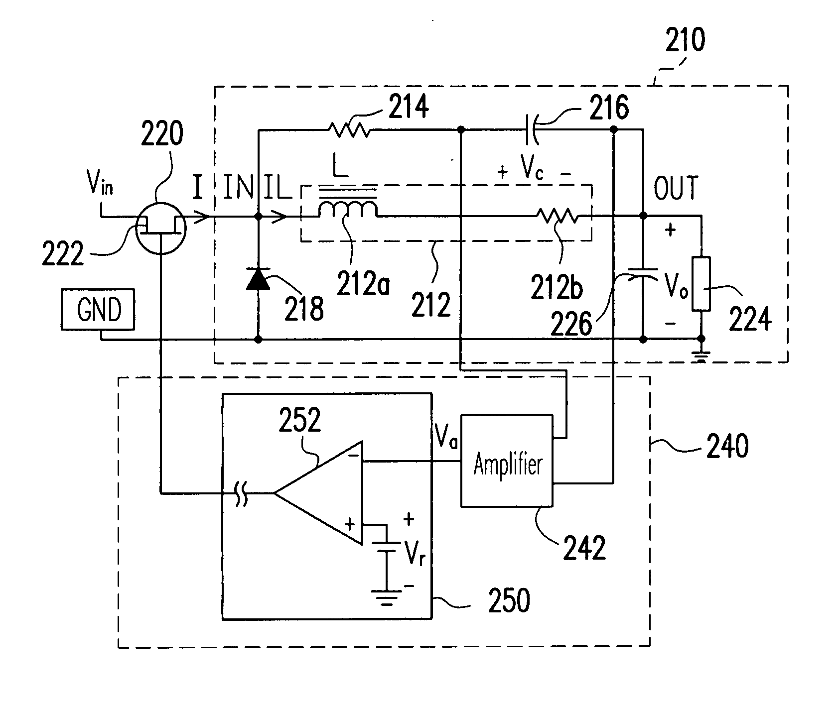
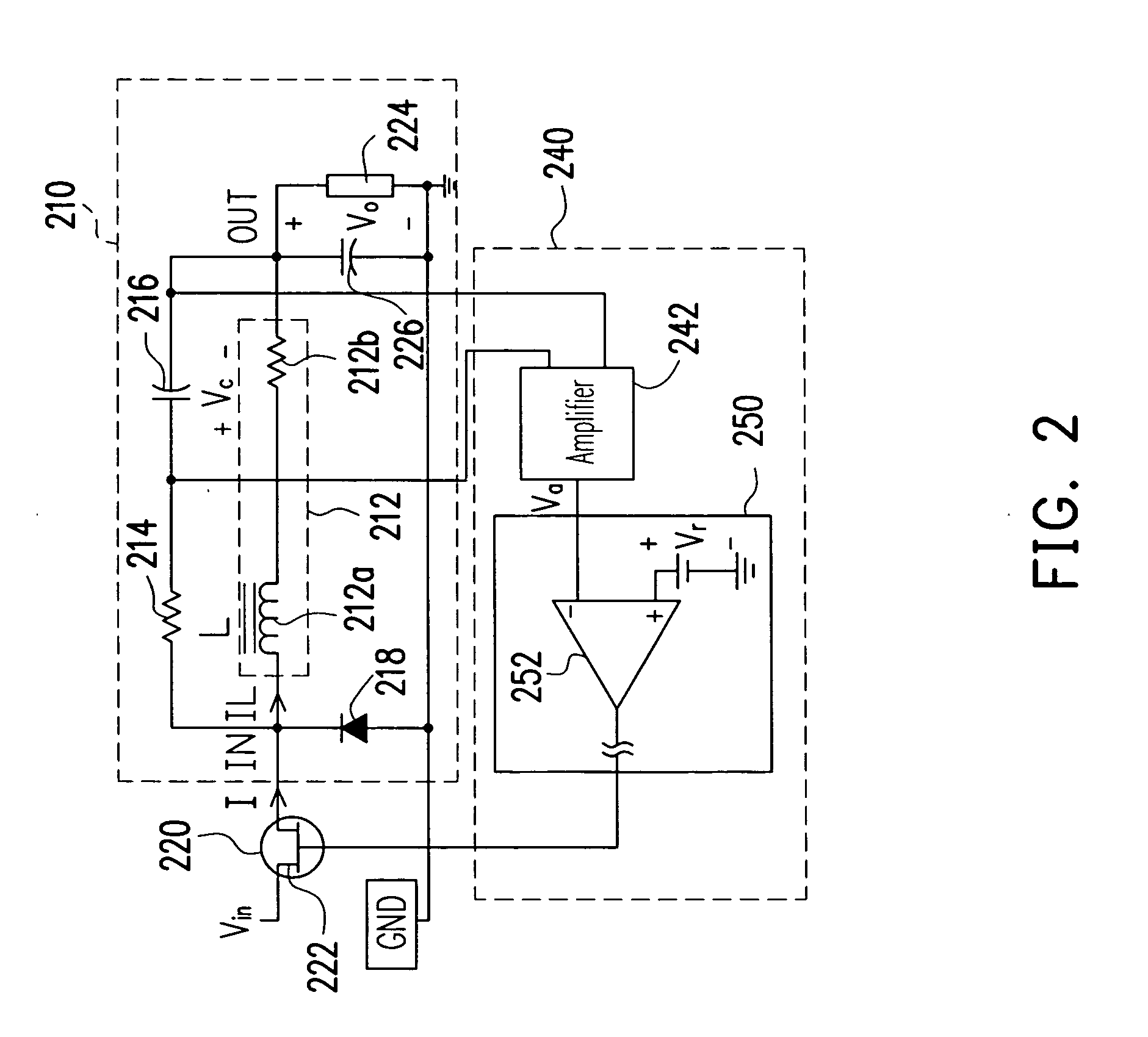
[0025]FIG. 2 is a schematic circuit showing a switching power converter according to an embodiment of the present invention. Referring to FIG. 2, the input of the switching power converter 200 is coupled to the input voltage Vin via the switch 220. Then the switching power circuit 210 converts the input voltage Vin into the output voltage Vo via the switch 220 for driving a load 224. The switching power circuit 210 is coupled to the input terminal of the current-limited protection circuit 240. The switch 220 determines whether to transmit the input voltage Vin to the input IN of the switching power circuit 210 according to the output of the current-limited protection circuit 240.

[0026] Referring to FIG. 2, the switch 220 comprises, for example, an NMOS switch transistor 222. The first source / drain terminal of the switch transistor 222 is coupled to the input voltage Vin, and the second source / drain terminal is coupled to the input terminal IN of the switching power circuit 210. The...


PUM


Abstract

A switching power converter comprises a switch, a pulse width modulation (PWM) circuit, a rectifying filter circuit and a current limited protection circuit. The input terminal of the rectifying filter circuit is coupled to an input voltage via the switch. The current limited protection circuit comprises an amplifier and a pulse-width modulator. The amplifier detects an induced voltage while a working current flows through the switching power converter, and amplifies the induced voltage so as to generate a comparison voltage. The pulse-width modulator receives an output from the amplifier, determines an output of the pulse-width modulator according the comparison voltage and a reference voltage, and limits the working current according to the output of the pulse-width modulator.

Description

BACKGROUND OF THE INVENTION [0001] 1. Field of the Invention [0002] The present invention relates to a current-limited protection circuit of a switching power converter, and more particularly to an amplifier for current-limited protection circuit of a switching power converter. [0003] 2. Description of the Related Art [0004]FIG. 1 is a schematic circuit of a prior art switching power converter. Referring to FIG. 1, the first source / drain terminal of the switch transistor 101 is coupled to the input terminal of the switching power converter for receiving the input voltage Vin. The second source / drain terminal is coupled to the output terminal of the switching power converter via the series inductor 103a and resistor 103b. A terminal of the diode 107 is coupled to the second source / drain of the switch transistor 101, and another terminal of the diode 107 is grounded via the resistor 109. The output terminal of the switching power converter is grounded via the capacitor 111. The output...

Claims


Application Information

Patent Timeline
Patent Type & Authority Applications(United States)
IPC IPC(8): G05F1/40
CPCG01R19/16571Y10S323/908H03K17/0822H02M1/32
Inventor LIN, JIAUN-LONGLEE, YEN-HUANGLO, JEN-CHI
Owner NAT CHUNG SHAN INST SCI & TECH
Why Eureka
Try Eureka