Vertical winding structures for planar magnetic switched-mode power converters

Active Publication Date: 2006-02-23
MYPAQ HLDG LTD
View PDF99 Cites 139 Cited by
  • Summary
  • Abstract
  • Description
  • Claims
  • Application Information

AI Technical Summary

Benefits of technology

[0009] The present invention provides a winding structure for planar integrated magnetics used in switched-mode power converters that maintains close coupling between the different windings but reduces the eddy current losses, lowers the DC winding resistance, reduces the number of layers of the printed circuit board (PCB)

Problems solved by technology

Transformers and inductors used within these power converters may be large and bulky and often limit their efficiency, power density and reliability.
However, the large interwinding capacitance between the outer-leg windings (16, 20, 18 and 22) and the center-leg inductor winding 24 may provide a low-impedance path from the integrated magnetic windings directly to the output of the converter, making the inductor windings ineffective in attenuating high-frequency noises and ripple.
Another potential disadvantage of a conventional planar winding de

Method used


Image

  • Vertical winding structures for planar magnetic switched-mode power converters
  • Vertical winding structures for planar magnetic switched-mode power converters
  • Vertical winding structures for planar magnetic switched-mode power converters

Examples


Embodiment Construction

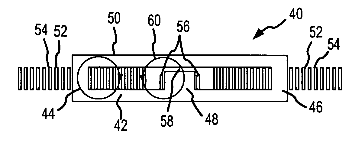
[0024] The present invention provides a “vertical” winding structure for planar magnetics used in switched-mode power converters that maintains close coupling between the different windings but reduces the eddy current losses, lowers the winding resistance, reduces the number of layers of the PCB, and in certain configurations reduces the capacitive coupling between the outer-leg windings and the center-leg windings, if one exists, of a magnetic core. This winding structure can be used in a wide range of magnetic structures including isolated and non-isolated CDRs, interleaved CDRs, and buck and boost converters. To maintain continuity, the vertical winding structure will be described in conjunction with a conventional E-I core for an isolated CDR.

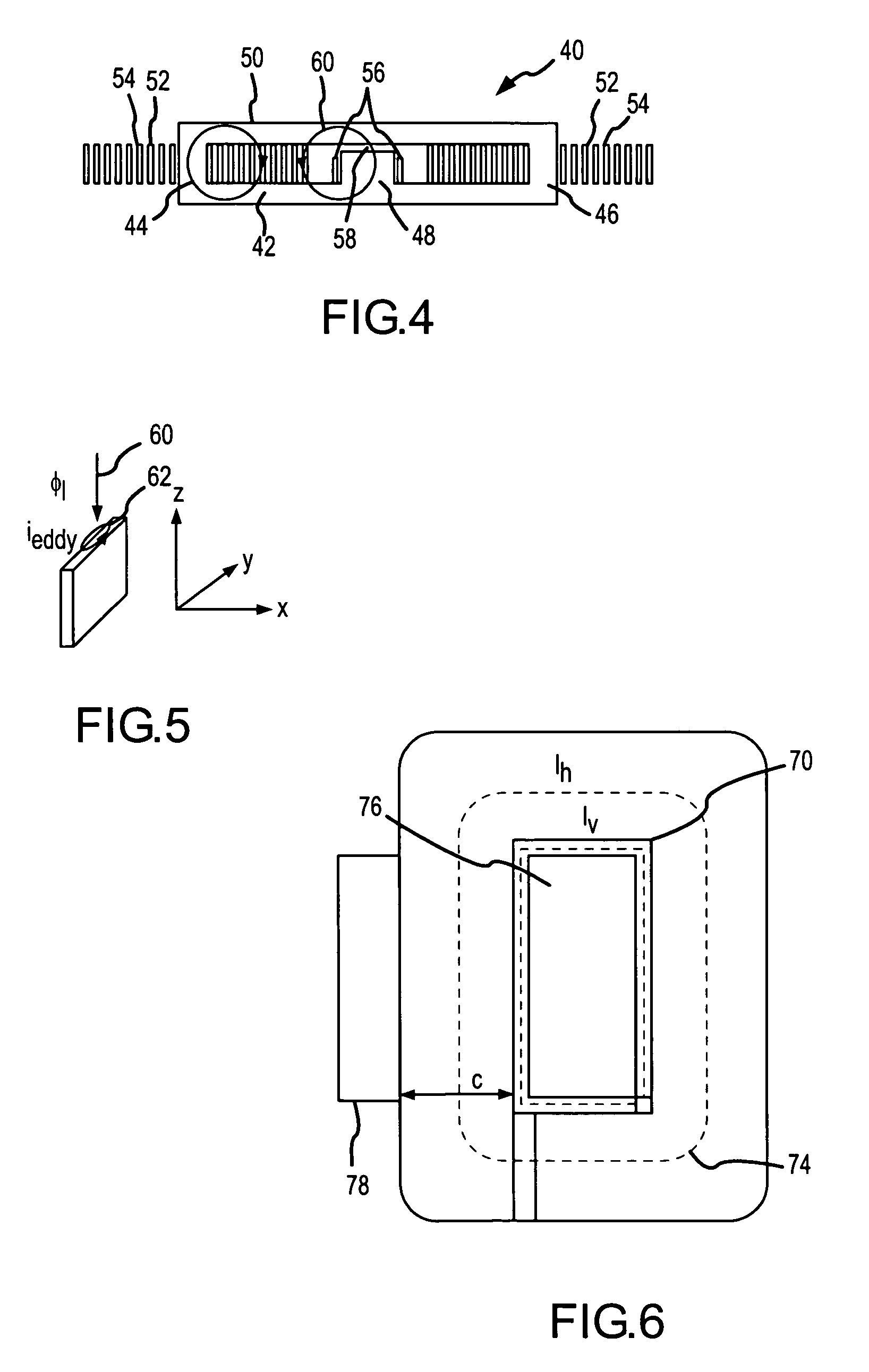
[0025] As shown in FIG. 4, the magnetic structure 40 for use with an isolated CDR includes an E-I core 42 having outer legs 44 and 46 and a center leg 48 and a plate 50. The split-primary and secondary windings are formed by interleaving ...


PUM


Abstract

A vertical winding structure for planar integrated magnetics used in switched-mode power converters maintains close coupling between the different windings but reduces the eddy current losses, lowers the DC winding resistance and reduces the number of layers of the PCB. Vertical and horizontal windings can be used together without sacrificing these performance advantages and further minimizing the capacitive coupling between the outer-leg windings and the center-leg winding. This winding structure can be used in a wide range of magnetic structures including isolated and non-isolated CDRs, interleaved CDRs, and buck and boost converters.

Description

BACKGROUND OF THE INVENTION [0001] 1. Field of the Invention [0002] This invention relates to planar integrated magnetics and more specifically to vertical winding structures for planar integrated magnetic switched-mode power converters. [0003] 2. Description of the Related Art [0004] Power converters are key components in many military and commercial systems and they often govern size and performance. Power density, efficiency and reliability are key characteristics used to evaluate the characteristics of power converters. Transformers and inductors used within these power converters may be large and bulky and often limit their efficiency, power density and reliability. These deficiencies can be improved by using a high frequency “switch-mode” architecture instead of a traditional step-down configuration and by replacing conventional core-and-coil designs with “planar magnetics”. [0005] Planar magnetics offer several advantages, especially for low-power dc-dc converter applications...

Claims


Application Information

Patent Timeline
IPC IPC(8): H01F27/02
CPCH01F27/255H02M3/28H01F27/2804
Inventor MEHROTRA, VIVEKSUN, JIANCHANDRASEKARAN, SRIRAM
Owner MYPAQ HLDG LTD
Why Eureka
Try Eureka