
Tunable spectral imaging filter configured for UV spectral ranges

Inactive Publication Date: 2006-02-23
CHEMIMAGE
View PDF14 Cites 18 Cited by
  • Summary
  • Abstract
  • Description
  • Claims
  • Application Information

AI Technical Summary

Benefits of technology

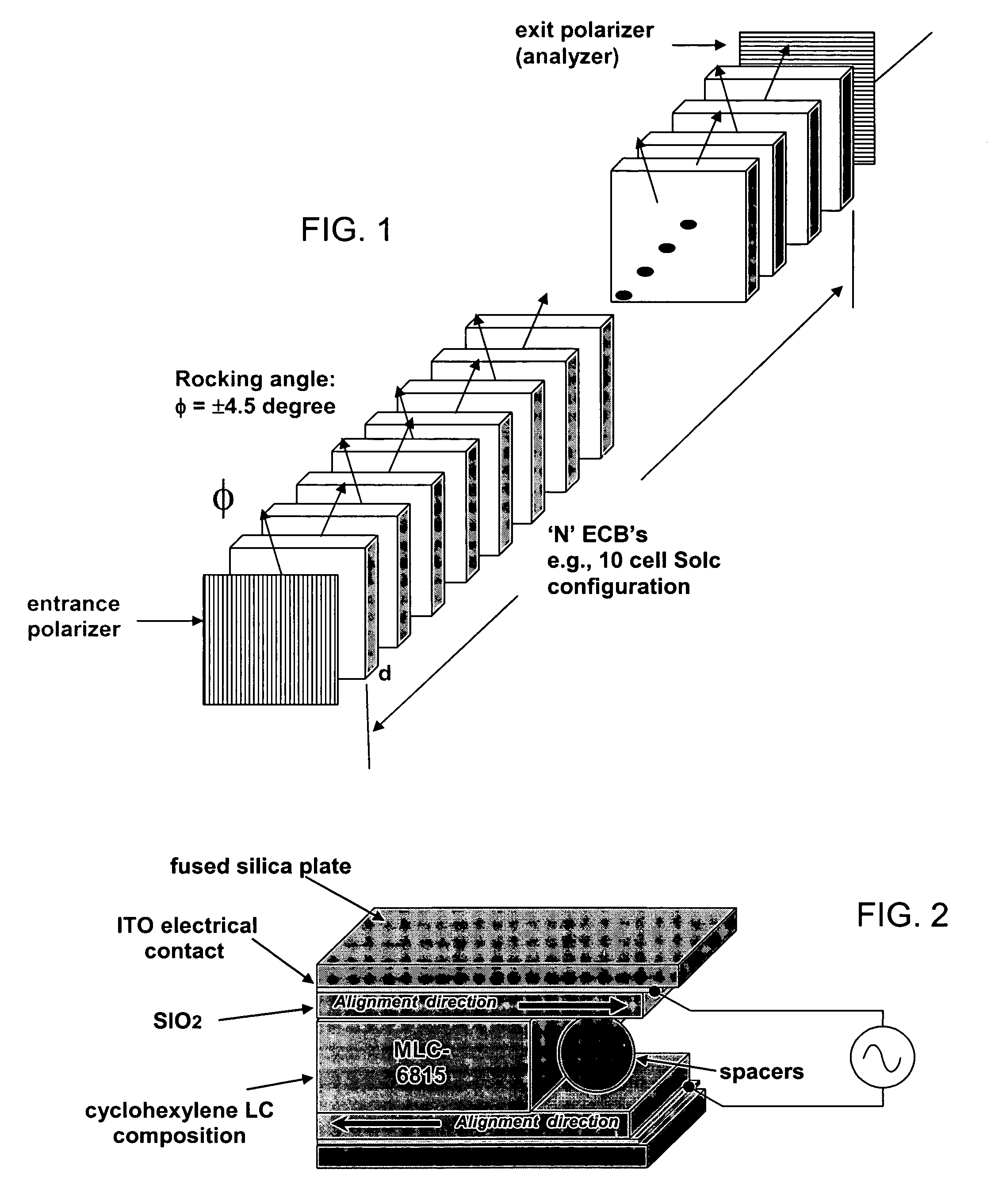
[0030] According to another aspect, a birefringent liquid crystal material having elongated rod component molecules is provided with a rigid portion that is based on a cyclohexylene rather than a phenylene structure, thereby providing rigidity and elongation but being substantially transparent up to a limiting short wavelength in the ultraviolet.
[0031] According to a further aspect, the structural components that support, align, electrically connect and adhesively adhered liquid crystal cells in a stack are each composed, selected and configured with one another to maintain and enhance UV transparency.

Problems solved by technology

There is a potential problem in attempting to image at UV wavelengths, however.
The multiple polarizers used in a Lyot filter tend to reduce the transmission ratio of the stacked filter element as a whole.
Generally, for stacked filter arrangements including Lyot filters and other configurations, it has not been possible to operate known wavelength bandpass filter stacks in the ultraviolet because the conventional elements used for tunable birefringence, namely liquid crystal elements, generally are absorptive in the ultraviolet band, e.g., 280 to 400ηm, where UV imaging might be useful for distinguishing the absorption spectra of element and compounds in a sample.
However, conventional liquid crystal cell compositions for stacked cell configurations are not transparent at ultraviolet wavelengths, e.g., 280 to 400ηm.
As a result, they are not practical as ultraviolet (UV) LCTFs.
In tuning for a wavelength at which a tunable birefringence retarder cell is even 90 or 95% transmissive at the tuned wavelength, but wherein there could be ten or twenty or more elements stacked, the available signal level becomes impractically low.

Method used


Image

  • Tunable spectral imaging filter configured for UV spectral ranges
  • Tunable spectral imaging filter configured for UV spectral ranges
  • Tunable spectral imaging filter configured for UV spectral ranges

Examples


Embodiment Construction

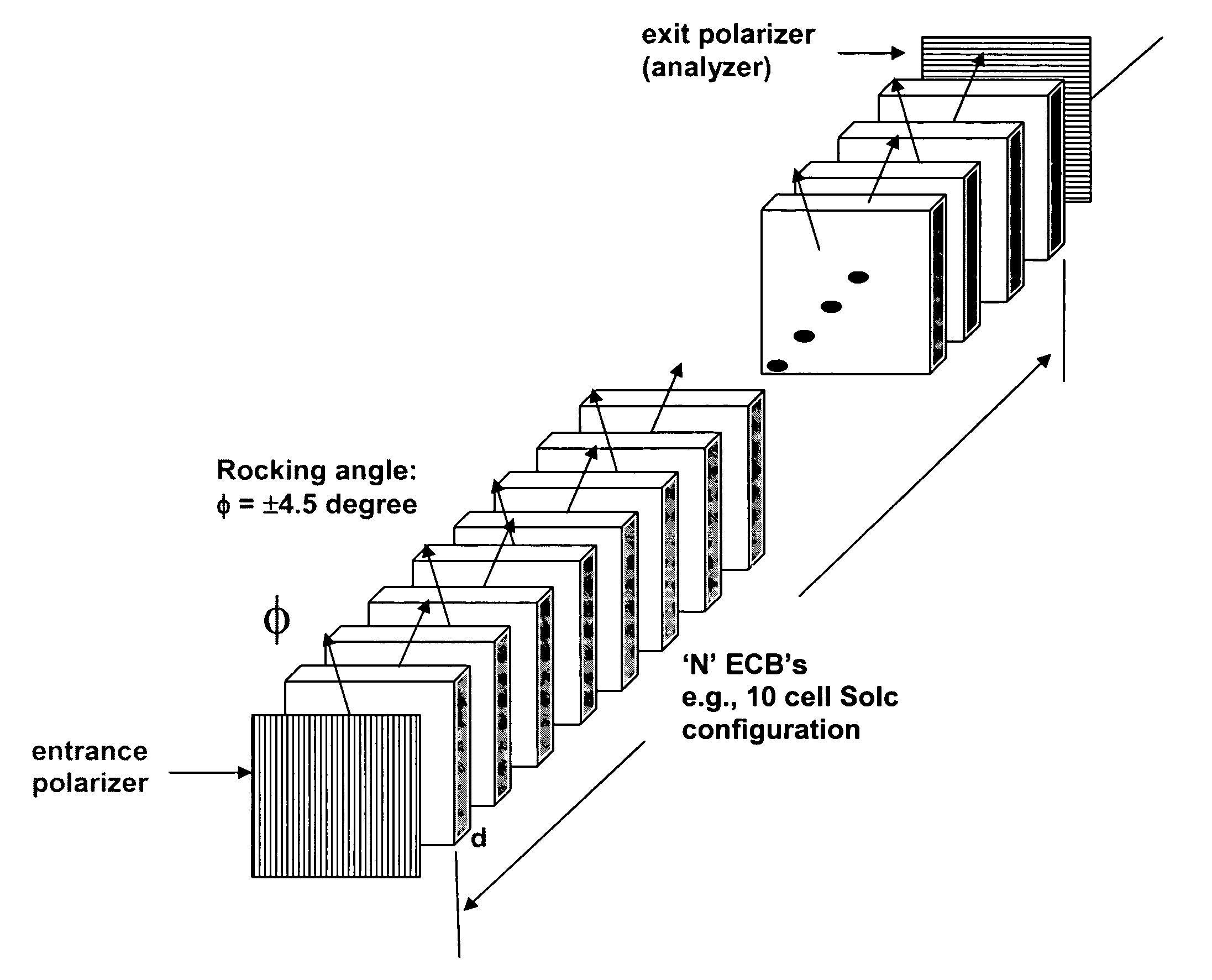
[0037] Referring to FIG. 1, the UV LCTFs (ultraviolet liquid crystal tunable filters) of the present invention, are shown, for example in a Solc stacked configuration. In this configuration, variable retardance cells of equal thickness (or effective thickness) are stacked between input and output polarizers. The retardance cells comprise tunable birefringent liquid crystal cells that are stacked and mounted along an optical propagation path together.

[0038] The depicted Solc configuration is intended as a nonlimiting example of a tunable UV filter configuration having two or more, and preferably a substantial number, of stacked cells that each contains a liquid crystal element. The invention is also applicable, for example, to other multiple cell stacked configurations such as Lyot, Evans split-element and hybrid configurations. The invention is also applicable to other operational types such as Fabry-Perot etalons containing tunable birefringence cells.

[0039] In imaging applicatio...


PUM


Abstract

A wavelength bandpass filter for chemical imaging and similar uses is configured to minimize absorption in ultraviolet wavelengths and arranged in a Solc, Lyot or similar arrangement of stacked controllable birefringent cells. A number of tunable liquid crystal cells are placed successively in a stack along an optical path, each of the cells having an electrically tunable birefringent element, wherein the cells are dimensioned and arranged at respective angular orientations for passing a tuned bandpass wavelength. A polarizer is arranged at least at an output end for controlling a polarization orientation of light. The liquid crystal cells each comprise at least one supporting plate, an alignment layer and birefringent layer, and wherein the liquid crystal cells are at least 90% transmissive over a UV wavelength tuning range between 280 and 400 ηm or larger.

Description

BACKGROUND OF THE INVENTION [0001] 1. Field of the Invention [0002] The invention relates to a tunable birefringent optical filter, especially for spectral imaging applications, using multiple stacked electrically tunable liquid crystal birefringent cells arranged together and with polarizers, for selective transmission at tuned wavelengths in the ultraviolet region. [0003] An electrically controlled birefringent liquid crystal element with a cyclohexyl based liquid crystal molecule structure renders the element substantially transparent at operational ultraviolet wavelengths, e.g., 280 to 400 ηm. The element is employed as a wavelength bandpass optical filter element in a stacked multiple element liquid crystal tunable filter configuration including one or more polarizers. The associated mounting, substrate plate, any included fixed retarder, the alignment layer, index matched glue, electrical contact and associated physical structures are also transmissive at ultraviolet, renderin...

Claims


Application Information

Patent Timeline
IPC IPC(8): G02F1/1335
CPCG01J1/0488G01J1/429G01J3/0224G01J3/26G01J2003/1213G02F2203/055G02B5/287G02F1/13G02F1/1395G02F2201/16G02F2202/40G02B5/283G01J3/447
Inventor WANG, CHENHUI
Owner CHEMIMAGE
Learn More