Laser emitting module, window cap, laser pointer, and light emitting module

a technology of laser pointers and laser beams, applied in the field of laser beam emitting modules, window caps, laser beams, and light beam emitting modules, can solve the problems of deteriorating the visibility of spot-lighted regions, affecting the brightness of laser beams, and affecting the output of laser beams

Inactive Publication Date: 2006-02-23
SONY CORP
View PDF7 Cites 11 Cited by
  • Summary
  • Abstract
  • Description
  • Claims
  • Application Information

AI Technical Summary

Benefits of technology

[0009] Further, in the technology disclosed in the above-mentioned Japanese Patent Application Publication H06-326380, a laser diode, optical resonator, battery drive circuit and the like are arranged discretely in single casing. Accordingly, a manufacture of such a laser pointer has to handle all elements and components thereof discretely, thereby causing an increase of risk for having dust adhered on respective elements and components during their assembly. Accordingly, a failure rate of products may be increase and service life thereof may be decreased. Further, because of a large number of the components, the number of assembling steps is increased. Further, as most of the components being optical parts, a precision alignment and careful assembly work are required.
[0034] Still further, by arranging such that an angle between the main direction of progression of the light and the oblique window plane of the window cap is adjusted not to allow the split reflected light from the optical filter to return to the optical resonator, it becomes possible to prevent the occurrence of the multi-reflection between the optical filter and the optical resonator, and to thereby limiting a spot light of the laser beam emitted from the window section to be a single convergence point.

Problems solved by technology

The output of laser beam substantially changes and becomes unstable when its operating temperature changes because of temperature dependency in the wavelength conversion, thereby causing deterioration of the visibility of a region spot-lighted while the laser beam the brightness of which varies unstably.
Further, a risk of injury to human body may increase due to an unexpected increase in the output of laser beam due to such a temperature change.
Accordingly, a manufacture of such a laser pointer has to handle all elements and components thereof discretely, thereby causing an increase of risk for having dust adhered on respective elements and components during their assembly.

Method used


Image

  • Laser emitting module, window cap, laser pointer, and light emitting module
  • Laser emitting module, window cap, laser pointer, and light emitting module
  • Laser emitting module, window cap, laser pointer, and light emitting module

Examples


first embodiment

[0051] As an application of a light emitting module according to an embodiment of the present invention, a laser emitting module, a window cap thereof and a laser pointer using the same will be described in detail with reference to the accompanying drawings. It should, however, be noted that the present invention is not limited thereto, and many other modifications and changes thereof may be considered within the scope of the present invention.

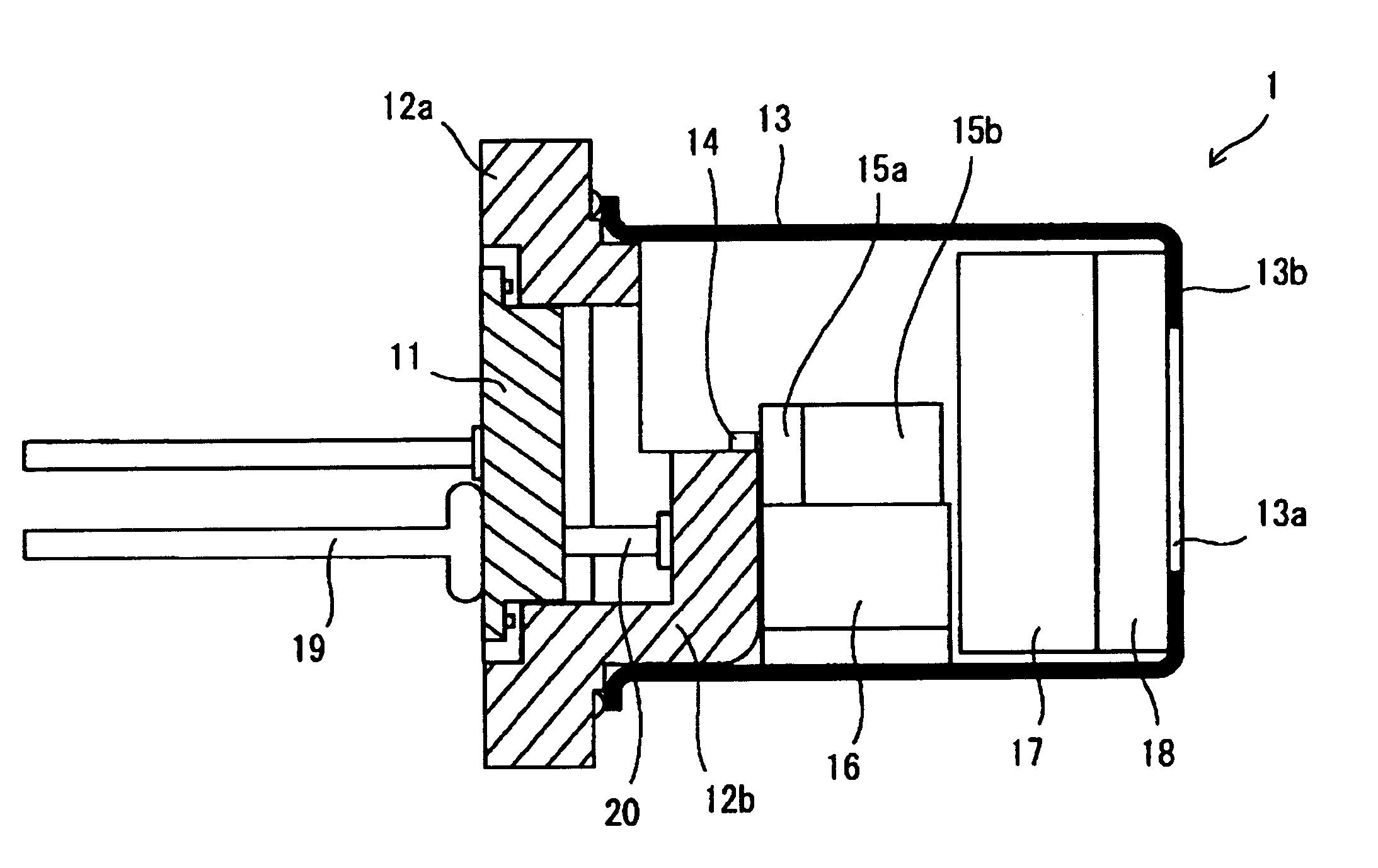
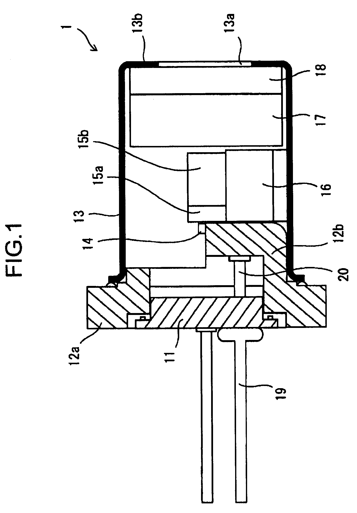
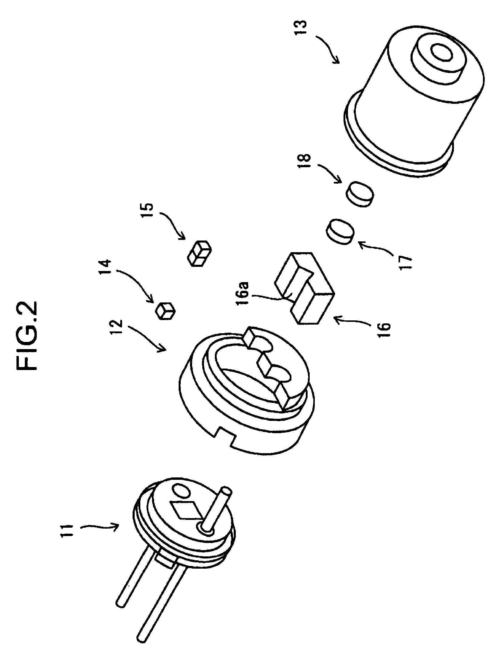
[0052] By referring to FIGS. 1 and 2, a configuration of a laser emitting module according to the present embodiment will be described. FIG. 1 is a schematic cross-sectional view, and FIG. 2 is an exploded perspective view thereof. A laser emitting module 1 has an outer shape formed from a header 11 to which a laser diode is to be attached, a heat sink 12 for dissipating heat to the outside, and a window cap 13 for protecting inside the module. Within the window cap 13, there are accommodated a laser diode 14 for emitting a light for exciting...

second embodiment

[0083] A laser emitting module, a window cap thereof, and a laser pointer using the same according to another embodiment of the present invention will be described by referring to the accompanying drawings. The present embodiment of the present invention differs from the present embodiment in that the intensity of a laser beam emitted is measured and its output power is controlled by an auto power control (APC) circuit.

[0084] The laser emitting module according to the present embodiment of the present invention will be described by referring to FIGS. 8 and 9. FIG. 8 is a schematic cross-sectional view thereof, and FIG. 9 is an exploded perspective view thereof. A laser emitting module 5 has an external configuration formed from a header 51 to which a laser diode will be attached, a heat sink 52 for conducting and dissipating heat to the outside, and a window cap 53 for protecting the inside the module. Within the window cap 53, there are accommodated a laser diode 54 for emitting a...


PUM

PropertyMeasurementUnit
wavelengthsaaaaaaaaaa
wavelengthaaaaaaaaaa

Abstract

A laser emitting module, a window cap thereof, a laser pointer using the same and a light emitting module are provided. A light emitted from a laser diode excites a solid-state laser medium so as to generate lights of different wavelengths, the wavelength of which is converted in a non-linear optical element so as to emit a laser beam of a short wavelength by second harmonic generation. An optical resonator including the solid-state laser medium and the non-linear optical element is supported by a base member. Heat of the laser diode and the optical resonator is dissipated via a heat sink which is in contact with the laser diode and the base member, thereby stabilizing temperatures of respective elements and thus the generation of the laser beam.

Description

CROSS REFERENCES TO RELATED APPLICATIONS [0001] The present invention claims priority to its priority document No. 2003-074345 filed in the Japanese Patent Office on Mar. 18, 2003, the entire contents of which being incorporated by reference herein. BACKGROUND OF THE INVENTION [0002] 1. Field of the Invention [0003] The present invention relates to a light emitting module that converts a wavelength of the light emitted from a light emitting element, and more specifically, it relates to a laser emitting module that uses a laser diode, a window cap and a laser pointer using the laser emitting module. [0004] 2. Description of Related Art [0005] In order to point a referring portion on a screen during a presentation or the like, a pointer capable of emitting a spot light is used. This type of pointer, as it uses a spot light for pointing the referring portion, has such advantages that it can point out any portion on the screen from a distance, and with easier in handling than a rod-like...

Claims


Application Information

Patent Timeline
Patent Type & Authority Applications(United States)
IPC IPC(8): H01S3/08G02B27/20G02F1/37G06K7/10G06K7/14H01S3/00H01S3/02H01S3/042H01S3/094H01S3/0941H01S3/109H01S3/16H01S5/02H01S5/022H01S5/024
CPCH01S3/005H01S3/0078H01S3/025H01S3/042H01S3/09415H01S5/02469H01S3/1611H01S3/1643H01S5/02212H01S5/02296H01S3/109H01S5/02257
Inventor AOSHIMA, MASAYOSHIOTANI, EIJI
Owner SONY CORP
Why Eureka
Try Eureka