Information reproduction method and information recording medium

a technology of information reproduction and information recording, applied in the field of information reproduction method and information recording medium, can solve the problems of difficult construction of apparatus to read both reflective signals and magnetic signals, low snr of reading signals, and decreased reading signals, etc., to achieve less expensive low-power, reduce the cost of low-power lasers, and increase the effect of absorption

Inactive Publication Date: 2006-02-23
HITACHI LTD
View PDF14 Cites 14 Cited by
  • Summary
  • Abstract
  • Description
  • Claims
  • Application Information

AI Technical Summary

Benefits of technology

[0018] An advantage of the method in (2) is that it can be used for magnifying reading of not only ROM and WO (write once) but also RAM (rewritable type) by using a phase-change material that changes between crystalline and amorphous states for a recording film because the recording marks are crystalline. A laser power at the time of magnifying reading can be made low compared to that for the method in (3), and a less expensive low-power laser can be used for a reproduction apparatus.
[0019] (3) The recording marks with larger absorption than that in non-recording area are formed in the recording layer. The reading layer is changed from crystalline to melt (amorphous) in an area corresponding to the recording mark by being irradiated with a light beam, and a magnified mark is formed there. At this time, the area in the reading layer corresponding to the recording mark is melted by heat conduction from the recording mark. When the magnified mark is formed, a reflective change occurs, thereby allowing information reproduction.
[0020] This principle is explained using FIGS. 18 and 19. FIG. 18 is a diagram of information reproduction according to (3). First, recording marks 174 with larger absorption and a reading layer 175 are formed. As to the size of the recording marks 174 in the spot traveling direction, a length of the shortest mark is below the diffraction limit. The reading layer is changed from crystalline to melt, i.e., amorphous, when reaching the melt temperature and forms a magnified mark 177. As shown in FIG. 19, the reading layer 175 has a property that its temperature rises in the area with larger absorption (recording mark) compared to the area with smaller absorption (other than recording mark) and amorphousization occurs from a lower read power. Owing to this property, when a spot 1 is focused on the recording mark 174 and the reading layer 175 of the information recording medium and the reading layer 175 is irradiated with a magnifying reading power 181, the reading layer in a crystalline state is amorphousized, centering the recording mark. Thus, a magnified amorphous area (magnified mark) 177 is formed in the spot, and a reflective change occurs in the area above the diffraction limit. This reflective change in the amorphous area (magnified mark) 177 is detected as a reading signal, thereby making it possible to read the recording mark below the diffraction limit.
[0021] There are two advantages in the method described in (3). One advantage is that reading is hardly influenced by an environmental temperature because a high magnifying reading power is used. The other advantage is that a process for preparing reading (crystallization) is unnecessary prior to the next magnifying reading because the reading layer crystallizes once the spot passes and the reading power is not irradiated to the reading layer any more.
[0022] According to the present invention, a medium with recording marks below the diffraction limit can be reproduced with a simple apparatus.

Problems solved by technology

Although reproducing methods that utilize the above super resolution and magnifying magnetic domain are capable of reading marks below the diffraction limit, each method has the following problems.
The method disclosed in patent document 1 that makes use of super resolution presents a problem that the amount of reading signals is decreased and SNR of reading signals becomes low because the optical aperture becomes smaller than the spot size.
The MAMMOS method disclosed in patent documents 2 and 3 presents a problem that it is difficult to construct an apparatus to read both reflective signals and magnetic signals because the apparatus not only requires a magnet and is complex but also does not simply read signals from reflective changes based on projections and depressions as ROM does.

Method used


Image

  • Information reproduction method and information recording medium
  • Information reproduction method and information recording medium
  • Information reproduction method and information recording medium

Examples


first embodiment

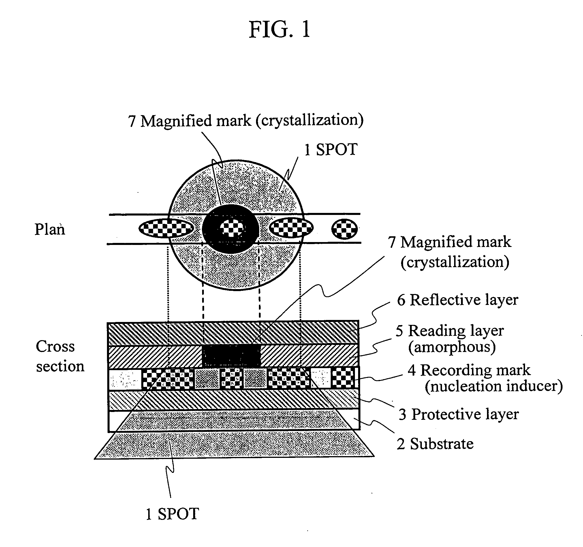
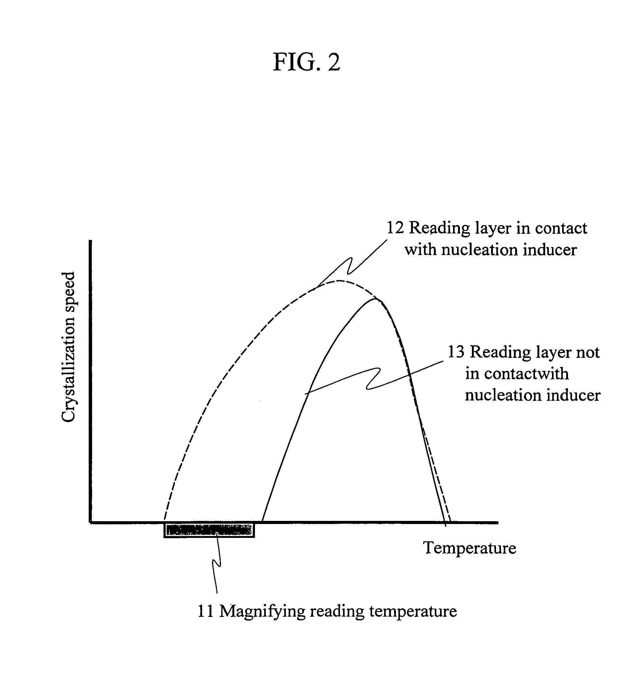
[0062] A first embodiment in which magnified marks are formed in a reading layer based on ROM recording marks composed of a nucleation inducer as described above in (1) is explained.

(Composition and Manufacturing Method of Information Recording Medium of the Present Invention)

[0063]FIG. 3 depicts a cross sectional structure of a disk-shaped information recording medium of the first embodiment of the present invention. This medium was manufactured as follows:

[0064] The processes for manufacturing the medium are shown in FIG. 4. First, in Process 1, a reflective layer 6 made of Ag98Pd1Cu1 with a thickness of 200 nm, a protective layer 8 made of Cr2O3 with a thickness of 20 nm, a reading layer 5 made of Ge6Sb2Te9 with a film thickness of 10 nm, a ROM recording mark material 31 made of Bi—Te—N with a film thickness of 20 nm, and a protective layer for ROM mark formation 32 made of SiO2 with a thickness of 20 nm were formed in turn by sputtering over a polycarbonate protective substr...

second embodiment

[0111] A second embodiment in which magnified marks are formed in a reading layer based on WO (write once) recording marks composed of a nucleation inducer as described above in (1) is explained.

(Composition and Manufacturing Method of Information Recording Medium of the Present Invention)

[0112]FIG. 9 depicts a cross sectional structure of a disk-shaped information recording medium of the second embodiment of the present invention. This medium was manufactured as follows:

[0113] The processes for manufacturing the medium are shown in FIG. 10. First, in Process 1, the reflective layer 6 made of Ag98Pd1Cu1 with a thickness of 200 nm, the protective layer 8 made of Cr2O3 with a thickness of 20 nm, the reading layer 5 made of Ge6Sb2Te9 with a film thickness of 10 nm, a WO recording mark material 91 composed of Si—Te—N and Ti—N with a film thickness of 20 nm, and a protective layer 3 made of ZnS—SiO2 with a thickness of 20 nm were formed in turn by sputtering over the polycarbonate pr...

third embodiment

[0125] A third embodiment in which magnified marks are formed in a reading layer based on ROM recording marks composed of a nucleation inducer as described above in (2) is explained.

(Composition and Manufacturing Method of Information Recording Medium of the Present Invention)

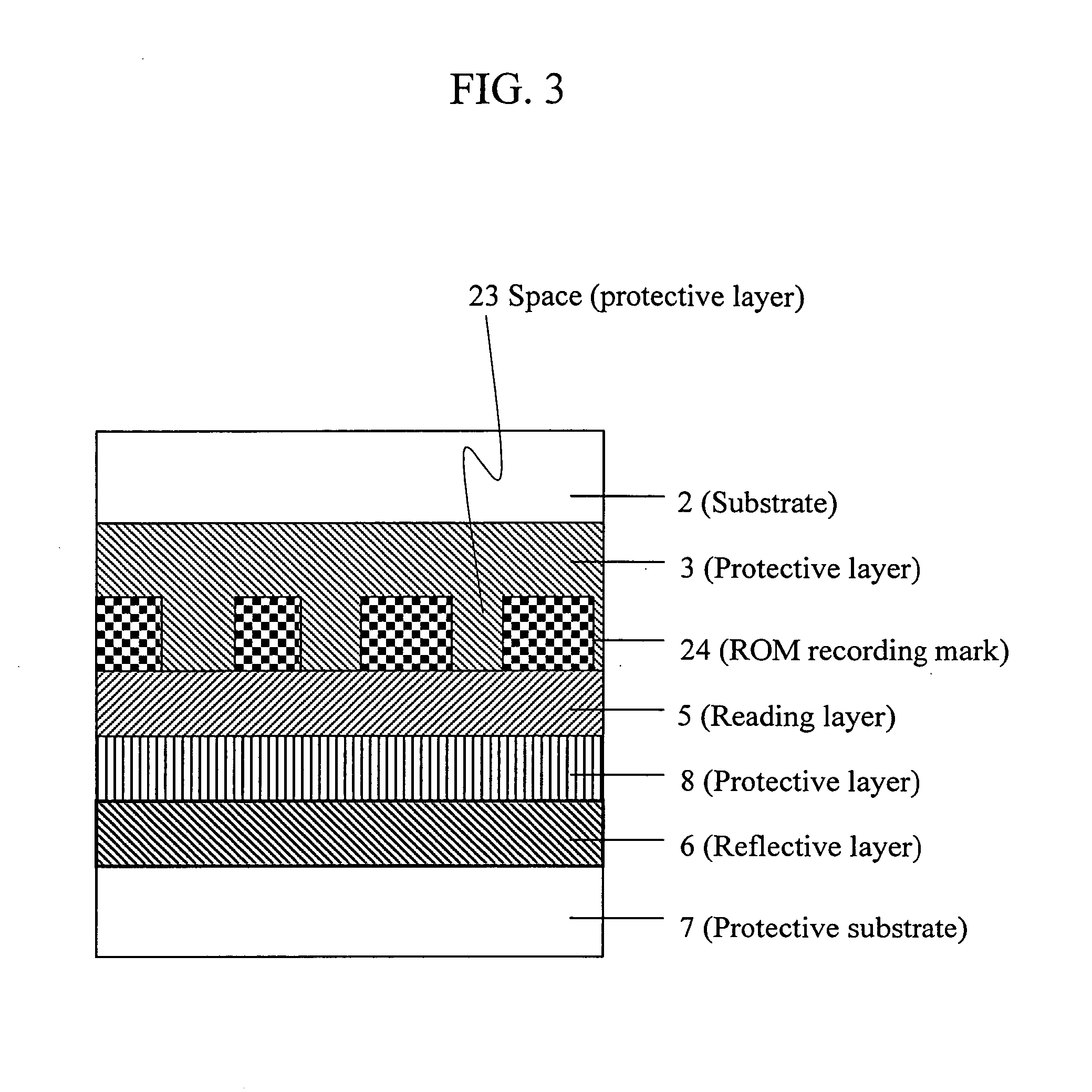
[0126]FIG. 13 depicts a cross sectional structure of a disk-shaped information recording medium of the third embodiment of the present invention.

[0127] The reflective layer 6 made of Ag98Pd1Cu1 with a thickness of 200 nm, the protective layer 8 made of Cr2O3 with a thickness of 20 nm, a reading layer 105 made of Ge5Sb70Te25 with a film thickness of 10 nm, a ROM recording mark material 122 composed of Sb—Bi with a film thickness of 20 nm, a protective layer 3 made of SiO2 with a thickness of 20 nm, and the substrate 2 made of an ultraviolet light curing resin with a thickness of ca. 0.1 μm were formed over the polycarbonate protective substrate 7 having a diameter of 12 cm, a thickness of 1.1 mm, and grooves...


PUM

PropertyMeasurementUnit
thicknessaaaaaaaaaa
thicknessaaaaaaaaaa
diameteraaaaaaaaaa

Abstract

Disclosed are an information reproduction method and an information recording medium that allow reproducing information below a diffraction limit. A recording layer formed with recording marks consisting of a nucleation inducer and a reading layer are provided. When a reading beam is irradiated, a predetermined area of the reading layer is crystallized based on the recording mark of the recording layer such that the area is magnified to a size larger than the recording mark, and information is thus reproduced. Information of the recording marks below the diffraction limit can be reproduced without using a special information reproduction apparatus.

Description

CLAIM OF PRIORITY [0001] The present application claims priority from Japanese application JP 2004-242064 filed on Aug. 23, 2004, the content of which is hereby incorporated by reference into this application. FIELD OF THE INVENTION [0002] The present invention relates to an information reproduction method and an information recording medium used for an optical disk. BACKGROUND OF THE INVENTION [0003] A variety of principles are known for recording information on a thin film (recording film) by means of irradiating a laser. Among them, a principle that an atomic arrangement is changed by laser irradiation as in phase-change (also called as phase-transition and phase-transformation) of a film material has come to be used. [0004] Generally, information recording media are composed of a first protective layer, a recording film made of GeSbTe type material and the like, an upper protective layer, and a reflective layer. Recording is conducted by making the recording film amorphous and e...

Claims


Application Information

Patent Timeline
Patent Type & Authority Applications(United States)
IPC IPC(8): B32B3/02G11B7/24G11B7/24067
CPCG11B7/00454G11B2007/24316G11B7/243G11B7/24
Inventor HIROTSUNE, AKEMIMINEMURA, HIROYUKIANZAI, YUMIKOSHINTANI, TOSHIMICHI
Owner HITACHI LTD
Why Eureka
Try Eureka