
Dynamically controllable biological/chemical detectors having nanostructured surfaces

a biological/chemical detector and nanostructure technology, applied in the field of biological/chemical detectors, can solve the problems of increasing the number of manual steps, and and achieve the effect of reducing the surface tension of the dropl

Active Publication Date: 2006-02-23
LUCENT TECH INC
View PDF14 Cites 55 Cited by
  • Summary
  • Abstract
  • Description
  • Claims
  • Application Information

AI Technical Summary

Benefits of technology

[0010] Movement of droplets of liquids across the nanostructured surfaces is achieved, in another embodiment, by varying the aerial density of the nanostructures on the nanostructured surface, thus causing a droplet to move to that area having the highest density of nanostructures. In yet another embodiment, this movement is achieved by sequentially applying a voltage to a plurality of electrodes, thus causing said droplet to move in a desired direction. In another illustrativ

Problems solved by technology

Specifically, as discussed previously, traditional systems often required multiple manual steps to accomplish the tasks of sample collection, separation and analysis.
While microfluidics applications, such as the aforementioned LabChip®, LILLIPUT chip and the NanoChip™ systems, significantly reduce the number of manual steps, they are limited in that a researcher must input samples manually, typically via pipette.
Such systems are also limited in that they require microchannels to transport liquids to test sites and, thus, are relatively inflexible in the destination to which the liquid is transported.
Additionally, while such microfluidics-based systems achieve a certain amount of integration over such traditional systems, such microfluidics-based systems still typically lack full integration of components.
Also, such microfluidics systems are typically characterized by relatively low sample throughput, relatively low component integration density, poor reliability, and often require substantial power to generate effective liquid flow actuation.

Method used


Image

  • Dynamically controllable biological/chemical detectors having nanostructured surfaces
  • Dynamically controllable biological/chemical detectors having nanostructured surfaces
  • Dynamically controllable biological/chemical detectors having nanostructured surfaces

Examples


Embodiment Construction

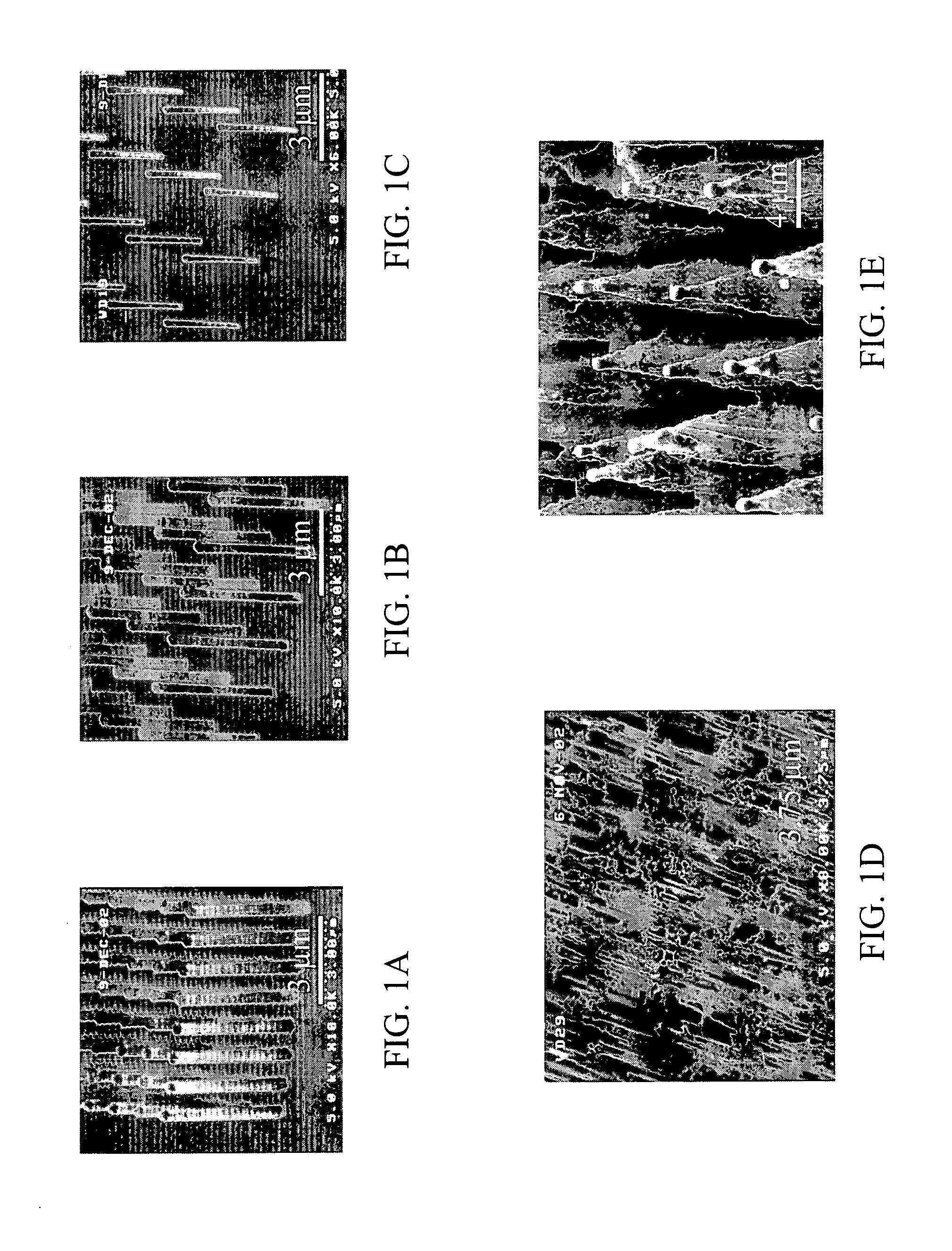
[0034] In the microfluidic chemical and biological detectors described above, reagent liquids are typically disposed in microchannels that are, illustratively, superhydrophobic, i.e., the surface of the microchannel is resistant to penetration by the liquids. FIGS. 1A-1E show different illustrative superhydrophobic surfaces produced using various methods. Specifically, these figures show surfaces having small posts, known as nanoposts and / or microposts with various diameters and with different degrees of regularity. An illustrative method of producing nanoposts and microposts, found in U.S. Pat. No. 6,185,961, titled “Nanopost arrays and process for making same,” issued Feb. 13, 2001 to Tonucci, et al, is hereby incorporated by reference herein in its entirety. Nanoposts have been manufactured by various methods, such as by using a template to form the posts, by various means of lithography, and by various methods of etching.

[0035] When a droplet of liquid, such as water, is placed...


PUM

PropertyMeasurementUnit
Densityaaaaaaaaaa
Electric potential / voltageaaaaaaaaaa
Biological propertiesaaaaaaaaaa

Abstract

A biological / chemical detector is disclosed that is capable of manipulating liquids, such as reagent droplets, without relying on microchannels. In a first embodiment, fluid flow is passed through the detector, thus causing particles wholly or partially containing an illustrative chemical compound or biological species to be collected on the tips of nanostructures in the detector. A droplet of liquid is moved across the tips of the nanostructures, thus absorbing the particles into the liquid. The droplet is caused to penetrate the nanostructures in a desired location, thus causing the chemical compound or biological species in said liquid droplet to come into contact with, for example, a reagent. In another embodiment, a fluid flow is passed through the nanostructured surfaces of the detector such that the chemical compound and / or biological species are deposited between the nanoposts of a desired pixel. A droplet of liquid is moved across the surface to that desired pixel and is caused to penetrate the nanostructures of the pixel, thus contacting a reagent.

Description

FIELD OF THE INVENTION [0001] The present invention relates generally to biological / chemical detectors and, more particularly, to dynamically controllable integrated biological / chemical detectors having nanostructured surfaces. BACKGROUND OF THE INVENTION [0002] Biological and chemical detector technology has become ever more important over the last several years and, as a result, has been undergoing dramatic growth. This growth is primarily fueled by the need for fast, highly sensitive and highly specific detector systems that would reduce false alarm rates and increase the ability to detect and identify chemical and biological species, such as chemical and biological warfare agents, in a wide range of environments. Currently, the majority of commercially-available chemical and biological agent detection systems rely on separate components or devices for sample collection, separation, and analysis. Thus, operation of such systems often requires multiple manual steps to accomplish, ...

Claims


Application Information

Patent Timeline
IPC IPC(8): C12M1/34B01L3/00B82B1/00G01N27/447G01N37/00
CPCB01L3/508B01L3/5088B01L2300/089B01L2400/0436B01L2400/0406B01L2400/0421B01L2400/0427B01L2300/161
Inventor ARNEY, SUSANNEKROUPENKINE, TIMOFEI NIKITALYONS, ALAN MICHAELMANDICH, MARY LOUISESCHABEL, MICHAEL J.TAYLOR, JOSEPH ASHLEY
Owner LUCENT TECH INC
Learn More