Combined-cycle power plant and steam thermal power plant

a technology of combined cycle and power plant, which is applied in the direction of steam engine plants, machines/engines, mechanical equipment, etc., can solve the problems of deterioration of reliability and environmental friendliness, increase in the amount of generated nitrogen oxides, and small progress, so as to achieve the effect of effectively utilizing the fuel produced

Inactive Publication Date: 2006-03-02
HITACHI LTD
View PDF6 Cites 21 Cited by
  • Summary
  • Abstract
  • Description
  • Claims
  • Application Information

AI Technical Summary

Benefits of technology

[0010] According to the present invention, it is possible to effectively ut

Problems solved by technology

However, progresses are not so noticeable in utilization of accompanying gases produced from medium- or small-scaled or overage gas fields and oil fields that have a difficulty in developing business by using pipelines or liquefying natural gas.
If the raw fuel is burnt in the gas-liquid mixed state, the combustion temperature rises locally due to a difference in amount of heat generated per unit volume between a liquid and gas to such a

Method used


Image

  • Combined-cycle power plant and steam thermal power plant
  • Combined-cycle power plant and steam thermal power plant
  • Combined-cycle power plant and steam thermal power plant

Examples


Embodiment Construction

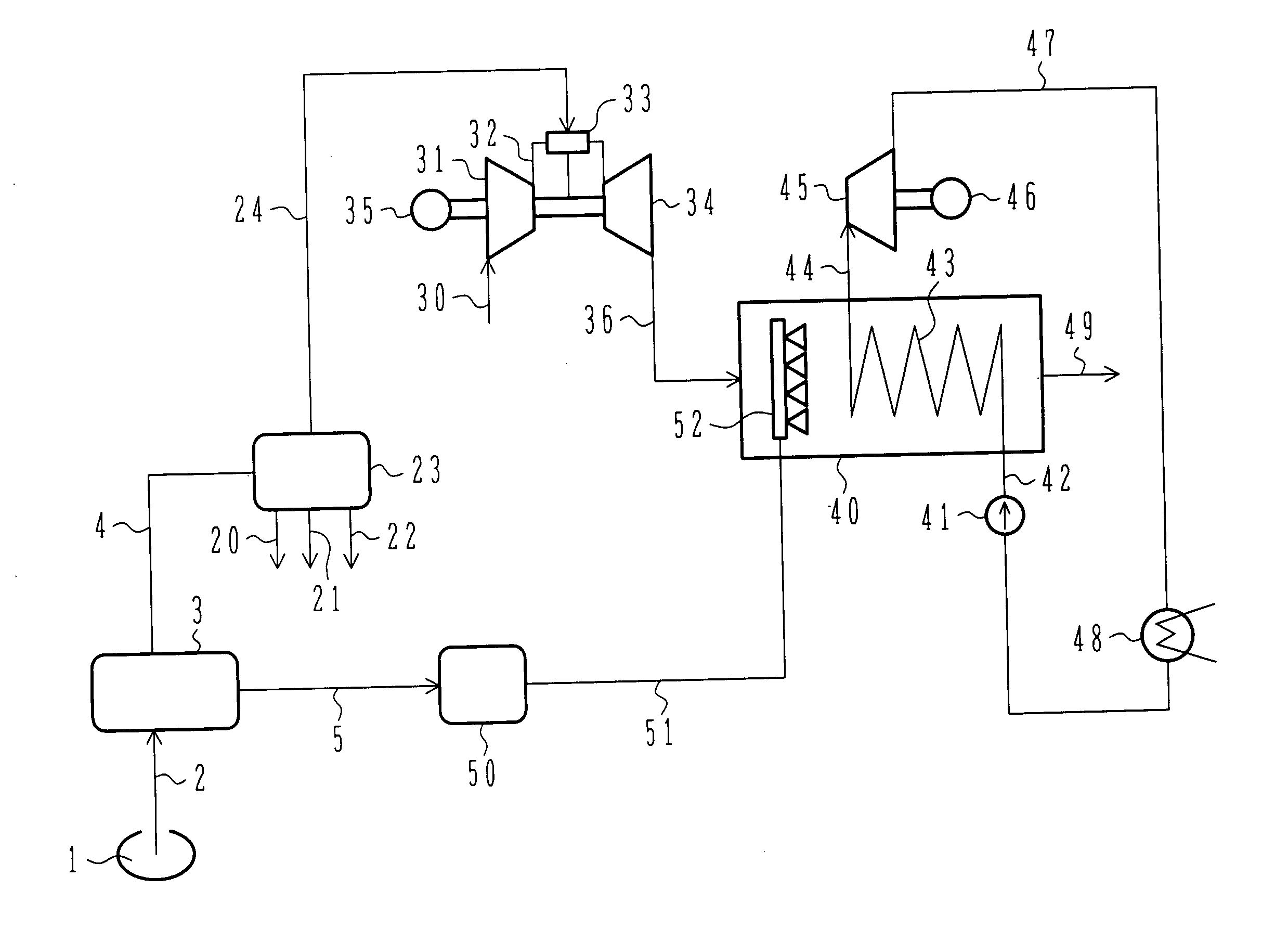
[0017] As a basic feature, a combined-cycle power plant of the present invention includes a combined-cycle power generating system comprising a gas turbine, a steam generator, and a steam turbine which are installed in the vicinity of a gas field or an oil field. Raw fuel produced from the gas field or the oil field is separated into gas and a liquid. Electricity is generated by using the separated gas as fuel for the gas turbine and the separated liquid as fuel for the steam generator. The generated electricity is supplied to a consuming area.

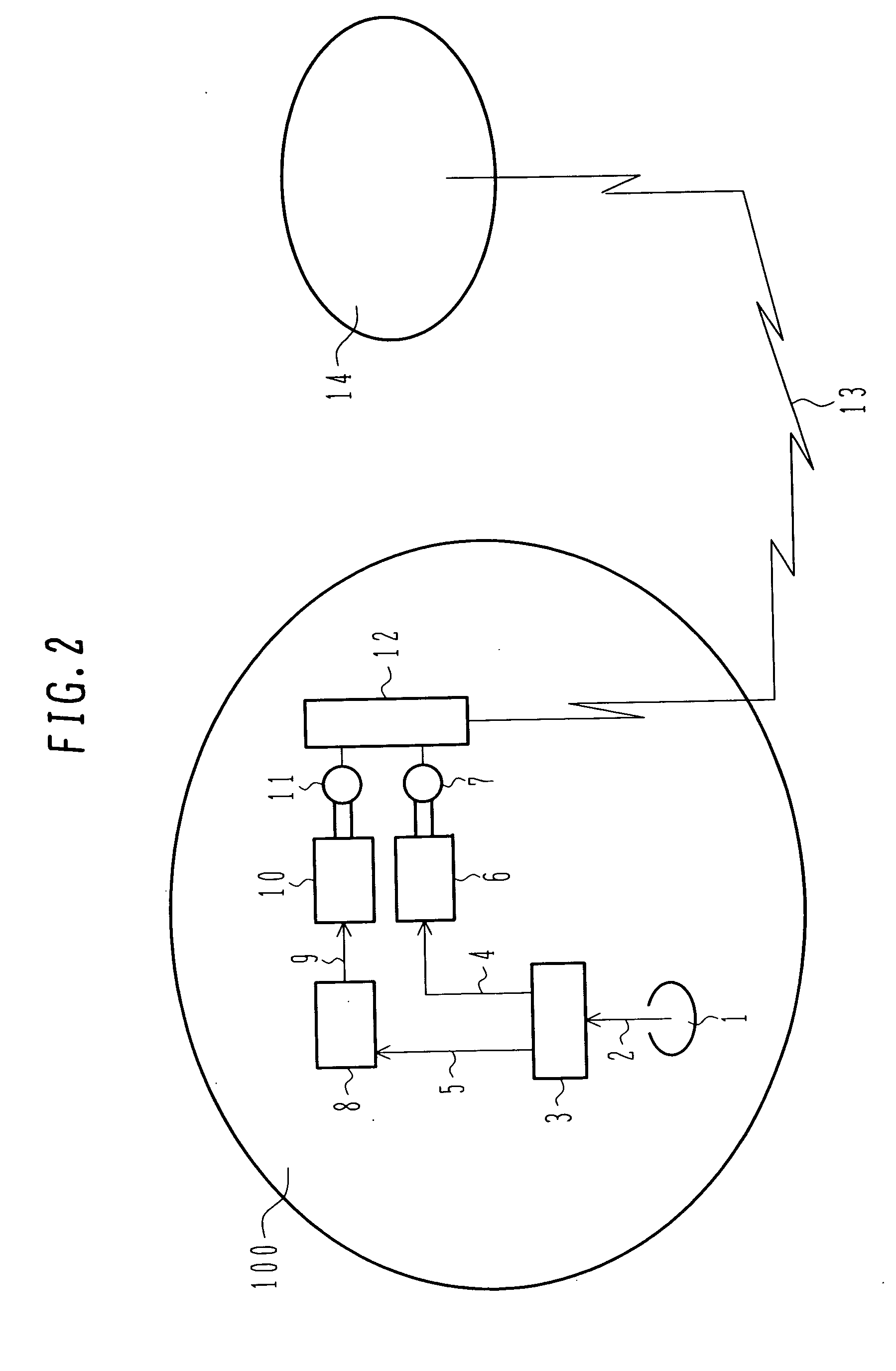
[0018] Embodiments of the present invention will be described in detail below with reference to the drawings, taking as an example the case of application to raw fuel produced from a gas field. FIG. 2 illustratively shows the construction of a combined-cycle power plant according to one embodiment, which is installed in the vicinity (indicated by 100) of a gas field 1. Raw fuel 2 produced from the gas field 1 contains a gas component and a li...


PUM


Abstract

A combined-cycle power plant, a steam thermal power plant, and a method for operating the power plant, which are capable of effectively utilizing raw fuel produced from medium- or small-scaled gas fields and oil fields. Raw fuel produced from a gas field is separated into a gas component and a liquid component by a separator. The gas component is burnt in a combustor of a gas turbine, and resulting motive power is converted to electricity by a power generator. The liquid component separated by the separator is burnt in a steam generator to generate steam that is supplied to a steam turbine. Resulting motive power of the steam turbine is converted to electricity by a power generator. Since the electricity generated by the power generators is AC power, the AC power is converted by a converter to DC power that is transferred from the vicinity of the gas field to a consuming area via a cable.

Description

BACKGROUND OF THE INVENTION [0001] 1. Field of the Invention [0002] The present invention relates to a combined-cycle power plant and a steam thermal power plant, which are installed near medium- or small-scaled gas fields and oil fields. More particularly, the present invention relates to a fuel line, a power generating system, and an operating method, which are used for burning raw fuel produced from gas fields and oil fields in a combined-cycle power plant or a steam thermal power plant. [0003] 2. Description of the Related Art [0004] In view of environmental pollution in worldwide scale, regulations on exhaust gases from various engines have been urged in progress. Under such situations, natural gas is worthy of note as fuel giving less influence upon environments. Natural gas is transported from a gas field to a consuming area, as shown in FIG. 1, by a method of liquefying the natural gas with a liquefaction facility in the gas field and transporting the liquefied gas to the co...

Claims


Application Information

Patent Timeline
IPC IPC(8): F02C6/18
CPCF01K23/10Y02E20/16F02C6/18
Inventor MARUSHIMA, SHINYAHORITSUGI, MUTSUMIFUKUMOTO, WASAO
Owner HITACHI LTD
Why Eureka
Try Eureka