Fluid-filled vibration damping device

a technology of vibration damping and flue gas, which is applied in the direction of shock absorbers, machine supports, mechanical equipment, etc., can solve the problems of dramatic loss of damping performance, difficult to realize the necessary damping properties, and difficulty in obtaining sufficient damping effects against vibrations with several or a wide range of frequencies, so as to prevent dramatic decreases in damping performance and effective damping effects

Inactive Publication Date: 2006-03-02
SUMITOMO RIKO CO LTD
View PDF9 Cites 22 Cited by
  • Summary
  • Abstract
  • Description
  • Claims
  • Application Information

AI Technical Summary

Benefits of technology

[0034] As will be apparent from the preceding description, the sealed fluid type of damping apparatus constructed according to the invention affords effective damping performance against vibrations input in the axis-perpendicular direction in the tuned frequency range of the orifice passage, based on the resonance action of the fluid flowing through the orifice passage, and pressure fluctuations in the fluid chambers are attenuated, based on the elastic deformation of the movable rubber layer, with respect to vibrations in put in the axis-perpendicular direction in the high frequency range over the tuned frequency range of the orifice passage. Thus, it is possible to prevent dramatic decreases in damping performance caused by the development of extremely high dynamic spring associated with substantial blockage of the orifice passage. It is thus possible to obtain effective damping effects in the tuned frequency range of the orifice passage as well as a broad range of frequencies in the high frequency range over the tuned range.

Problems solved by technology

However, a problem with the fluid-filled vibration damping device structured in the above manner is the narrow range of frequencies in which it is possible to effectively bring about damping effects on the basis of the resonance action of the fluid flowing through the orifice passage.
It is thus difficult to obtain sufficient damping effects against vibrations with several or a wide range of frequencies, and difficult to realize the necessary damping properties.
A major problem in particular is the dramatic loss of damping performance upon the development of extremely high dynamic spring associated with increased flow resistance in the orifice passage when the input vibrations are of a higher frequency range than the frequency range for which the orifice passage has been tuned.
However, problems with this damping device are that the incorporation of the actuator results in an extremely complex structure which is difficult to manufacture, as well as in higher costs and larger sizes.
However, because the thin-walled component is formed by the rubber elastic body itself elastically connecting the inner shaft and outer cylinder in this damping device, providing the thin-walled component runs the risk of adversely affecting the spring properties of the damping device.
Furthermore, because the thin-walled component is formed by the rubber elastic body itself elastically connecting the inner shaft and outer cylinder, input vibrations directly cause elastic deformation of the thin-walled component.
It is thus difficult to make the thin-walled component thin enough when attempting to realize the spring properties required of the damping device and ensure the durability of the thin-walled component.
It is therefore sometimes difficult to effectively obtain low dynamic spring effects based on pressure fluctuation absorbing action with this type of thin-walled component.

Method used


Image

  • Fluid-filled vibration damping device
  • Fluid-filled vibration damping device
  • Fluid-filled vibration damping device

Examples


first embodiment

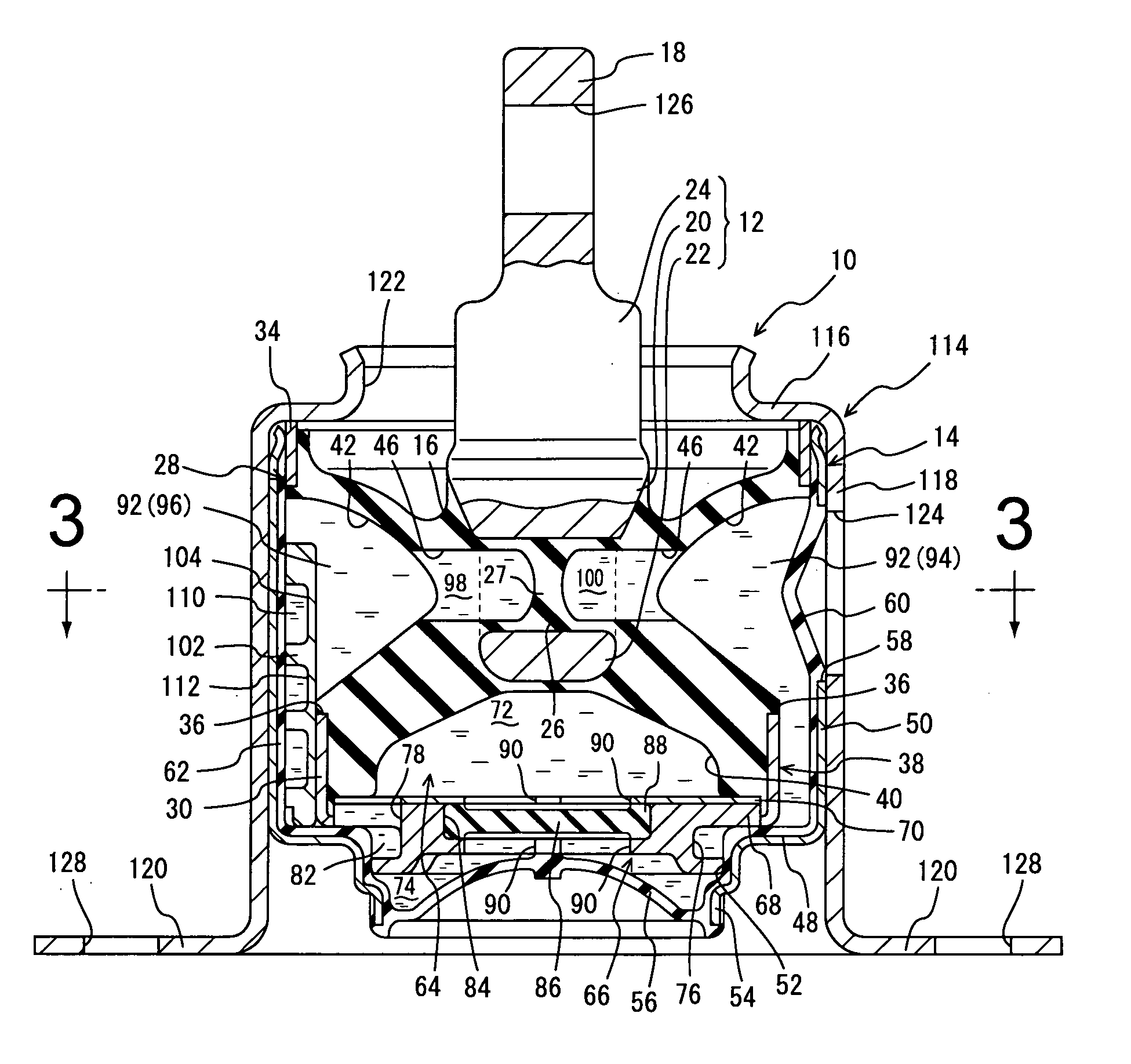
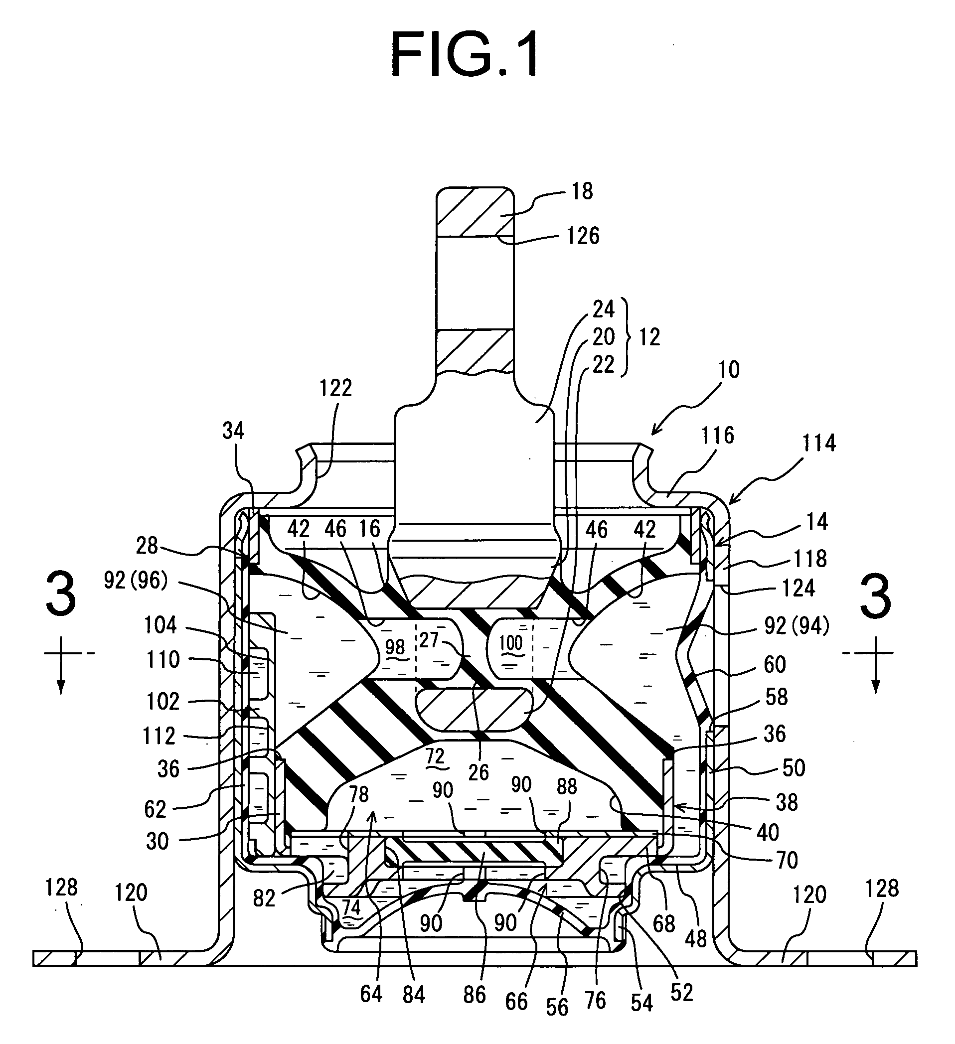
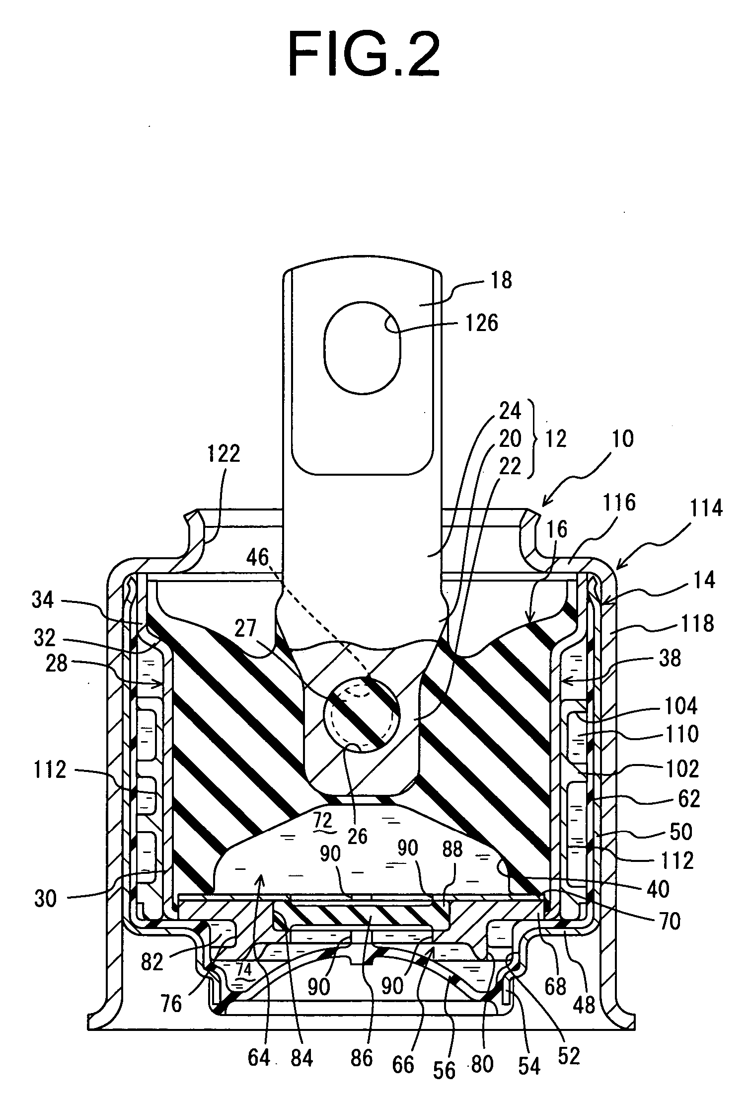
[0047]FIGS. 1-3 illustrate an engine mount 10 for use in an automotive vehicle of construction according to the invention. This engine mount 10 has a construction wherein a metallic inner shaft member 12 serving as the inner shaft and a metallic outer cylindrical member 14 serving as the outer cylinder are disposed apart, the inner shaft member 12 and outer cylindrical member 14 being elastically linked by means of a rubber elastic body 16, with the inner shaft member 12 attached to the automobile power unit and the outer cylindrical member 14 attached to the automobile body, so that the power unit is supported in a vibration-damped manner relative to the body. The engine mount 10 in this embodiment is mounted with the vertical direction in FIG. 1 being in a generally perpendicular vertical direction. As a rule, in the following description, the vertical direction refers to the vertical direction in FIG. 1.

[0048] More specifically, the inner shaft member 12 is in the shape of a soli...

second embodiment

[0094]FIGS. 8-10 illustrate a damping bushing 130 in the invention. In the damping bushing 130, a metal sleeve 134 and an inner shaft member 132 as the inner shaft disposed radially apart from each other are linked by a rubber elastic body 136, and an outer cylindrical member 138 as the outer cylinder is fitted and fixed to the metal sleeve 134. The damping bushing 130 is mounted between members joined in a damped manner by attaching the inner shaft member 132 and outer cylindrical member 138 to one of the members joined in a damped manner.

[0095] More specifically, the inner shaft member 132 is, in the form of a solid small diameter rod, an attachment fixing portion 140 being integrally formed with both axial ends. A through hole 142 is formed in the inner shaft member 132, passing axis-perpendicularly through the intermediate portion. In this embodiment, the through hole 142 is formed so as to extend straight in the axis-perpendicular direction of the inner shaft member 132, with a...


PUM


Abstract

A fluid-filled vibration damping device including: a rubber elastic body interposed between and elastically connecting an inner shaft and an outer cylinder; a pair of fluid chambers having an non-compressible fluid sealed therein and formed facing on both sides, in the inner shaft axis-perpendicular direction; an orifice passage through which the pair of fluid chambers communicate with each other; a through hole formed through the inner shaft in the axis-perpendicular direction; and a movable rubber layer fluid-tightly closing the through hole and being exposed at opposite major surfaces thereof to the pair of fluid chambers, respectively so that pressure in the respective fluid chambers are exerted against the major surfaces of the movable rubber layer.

Description

INCORPORATED BY REFERENCE [0001] The disclosure of Japanese Patent Application No. 2004-249178 filed on Aug. 27, 2004 including the specification, drawings and abstract is incorporated herein by reference in its entirety. BACKGROUND OF THE INVENTION [0002] 1. Field of the Invention [0003] The present invention relates to a fluid-filled vibration damping device in which damping effects are obtained based on the flowing action of a fluid sealed in the interior, and in particular relates to a fluid-filled vibration damping device which is suitable for use as automobile engine mounts or body mounts, differential mounts, and suspension bushes. [0004] 2. Description of the Related Art [0005] JP-U-4-43636 discloses one type of known damping device used as a damping connector or damping support mounted between members forming a vibration transmission system. The disclosed damping device includes an inner shaft and outer cylinder disposed radially apart from each other, which are connected b...

Claims


Application Information

Patent Timeline
Patent Type & Authority Applications(United States)
IPC IPC(8): F16F5/00
CPCF16F13/10F16F13/108F16F13/105
Inventor TANAKA, EIJI
Owner SUMITOMO RIKO CO LTD
Why Eureka
Try Eureka